Site Links
Howdy, Stranger!
It looks like you're new here. If you want to get involved, click one of these buttons!
Quick Links
Categories
In this Discussion
Who's Online (0)
2.5 WAY W/SUB using 2 KABD

Hello. I'm the new guy and already have a question. I was pointed towards these forums because I was told there were a couple of ppl that were good with these boards so hopefully they can help. I have a MTM setup plus a sub. Previously I built the speakers with passive crossovers in a 2.5 way config but could never quite get it where I wanted it. This setup had my sub on its own monoblock amp. I now have 2 KABD 4100s and I'm in very new territory with these amps and DSP. After a lot of messing around I actually have the speakers sounding better than they ever have but the sub is somewhat lacking. I have it bridged and connected to J13 with J14 free but only as a woofer. My question is, what can I do to this setup to get more out of my sub. It used to rattle windows now it barely gives me anything. Can I somehow rig one of these boards to create a sub out? Should I be using J14 or both maybe? Is there anything I need to do in Sigma to make the woofer into subwoofer? If so, what? I dont have the expertise to create my own setup so for now, I'm modifying pre existing setups provided by Dayton. I can provide my present setup if needed. Thanks for reading
Comments
So many questions, so few details! So, let’s first take a few steps back and get some needed information.
Which Dayton project are you using? I see three 2.1 projects. I assume you have a DSP programmer board and have used it to modify the SigmaStudio project.
Do you want to use pots to control volume? The “Simple 2.1 EQ Project” uses one pot to control master volume and another pot to independently control the sub. In other projects pots are used as tone controls and select crossover points. You can delete these controls, e.g. delete the master volume control and let your source control the volume.
Have you thoroughly read and understand the user manual? The most important part is understanding how the J13 and J14 wiring determines if the outputs are stereo or mono. If you use the “Simple 2.1 EQ Project” J14 would be wired as stereo and J13 as mono.
A few notes:
None of the example 2.1 projects have a crossover for your MTM speakers. In the “Simple 2.1 EQ Project” you’d need to replace the “J14 PEQ” with a 2-way crossover.
For a single sub system one board will drive the sub and the other board’s sub output will be unused.
The Dayton KABD-4100 is the same as the Sure/Wondom JAB5. You can find Youtube videos about the JAB5 from Wondom (LINK).
Expect to spend some time learning SigmaStudio. A good place to start is their Wiki (LINK).
Good luck!
Thank you for taking the time to respond. I'll answer in the order asked
1. At present time I am using the 3 way via cascaded setup after not having much luck with the 2.1since, as you stated, there is no crossover support. I also like the idea of handling each driver or in my case the Tweeter and 2 woofers separately..
2. The pots are not overly important other than main volume. I use a mini PC as my AVR and have Peace Eq installed on it that I run all my music through. So, individual pots to adjust bass and/or treble gains isnt needed since Peace has all of that
3. I have a basic understanding of what the user manual says. Unfortunately, I find the user manual lacking in how to do some things. Its possible that I am lacking in comprehension. I'm more of a youtube guy. If I watch it get done, I understand it
I thought I had read somewhere that the JAB5 wondom was the same. I just wasnt sure how much Dayton had deviated from that design. I was looking at both the JAB5 and something similar from Tinysine
I do have the programmer and have a modified config of the 3 way setup mentioned above downloaded. I just havent had any luck getting it to push my sub the way I want it yet. I guess I was taking the easy way out with trying to hook my monoblock back up to it. Currently the woofers are wired in parallel and each parallel circuit has its own channel as do the tweeters. That takes up the 4 channels on the first board. The 2nd slave board just has the sub bridged with the jumper wires for mono/stereo not connected to one another using J13 with J14 empty. This is just configured as a woofer channel. I'm still unsure how to configure it as a subwoofer channel if that will help
I have considered building another sub but the one I have now...a 12" in a true (within 2 cms) quarter wave TL and it never fails to put a smile on my face when it comes to hitting them low sub 30Hz frequencies. I've never heard anything like it but it's big and I dont have room for its twin.
I believe I will go to Sigmas wiki and try to figure this out. I'd really like to break away from the premade setups and just create something for the 2nd board but any advice you can impart would be welcomed and appreciated
>
Thank you for taking the time to respond. I'll answer in the order asked
1. At present time I am using the 3 way via cascaded setup after not having much luck with the 2.1since, as you stated, there is no crossover support. I also like the idea of handling each driver or in my case the Tweeter and 2 woofers separately..
2. The pots are not overly important other than main volume. I use a mini PC as my AVR and have Peace Eq installed on it that I run all my music through. So, individual pots to adjust bass and/or treble gains isnt needed since Peace has all of that
3. I have a basic understanding of what the user manual says. Unfortunately, I find the user manual lacking in how to do some things. Its possible that I am lacking in comprehension. I'm more of a youtube guy. If I watch it get done, I understand it
I thought I had read somewhere that the JAB5 wondom was the same. I just wasnt sure how much Dayton had deviated from that design. I was looking at both the JAB5 and something similar from Tinysine
I do have the programmer and have a modified config of the 3 way setup mentioned above downloaded. I just havent had any luck getting it to push my sub the way I want it yet. I guess I was taking the easy way out with trying to hook my monoblock back up to it. Currently the woofers are wired in parallel and each parallel circuit has its own channel as do the tweeters. That takes up the 4 channels on the first board. The 2nd slave board just has the sub bridged with the jumper wires for mono/stereo not connected to one another using J13 with J14 empty. This is just configured as a woofer channel. I'm still unsure how to configure it as a subwoofer channel if that will help
I have considered building another sub but the one I have now...a 12" in a true (within 2 cms) quarter wave TL and it never fails to put a smile on my face when it comes to hitting them low sub 30Hz frequencies. I've never heard anything like it but it's big and I dont have room for its twin.
I believe I will go to Sigmas wiki and try to figure this out. I'd really like to break away from the premade setups and just create something for the 2nd board but any advice you can impart would be welcomed and appreciated
OK, I have a basic idea of what you're doing now, one board (the master) to drive both L&R for the two MTMs and one board (the slave) to drive just the sub. I assume you have the cable for the I2S lines between the 2 boards installed and you're getting at least some output from the sub. Right?
One problem with the slave (i.e. sub) project: It's using only the right channel so you need to modify the "input" control to use both I2S channels and mix them together. I'd also add a volume control for that board to control the sub volume independently. If you want, I could create modified versions of both projects for you to start with.
Here's something to try - I modified the stereo 3-way master project to a dual 2-way master project. Just download the .zip file and rename the extension from .zip to .dspproj.
Thank you. I will get it over to my mini right away. And yes, you are correct. That is what I am trying to do.
Apparently, that file is empty according to Windows anyway. I understand what you are doing though and messed around in it a little. Do you have to set the slave board as such in Sigma or does it recognize master/slave by the slider position?
He mentioned renaming the file, changing the extension. So not a true compressed file.
I'm trying to but it doesnt give me the .zip when i download it. Just names the file. I dont know why I cant get it to show
Never mind. I figured it out. Jeez...
Pesky windows hiding extensions.
I forgot about Windows hiding file extensions since I turned that off eons ago. Glad you figured it out. The master/slave settings are set by the switches alone. Here are a couple of updated projects (rename each to .dspproj as before):
Dual 2-way Subwoofer controls Master I2s.zip - I added subwoofer controls (crossover, volume control, etc.) to the project. This could be easily updated to use a pot to control the sub volume.
Mono Subwoofer Slave via cascaded KABD-4100.zip - Amplifies the sub signal and feeds it via J13 in bridged mode.
You'll notice the Mono Subwoofer project is just a feedthrough, no controls at all. That way you'll only have to deal with the Master project when making changes.
It does seem like a waste of your 2nd KABD just to use it as an amp. You could connect a cheap PCM5102 DAC board to the master's I2S lines and use your mono-block amp. I've done that and can help with the details if you choose that path.
yeah,it kind of is and probably wont stay that way. I'm hoping to learn more about this and be able to set it up differently in the future. I really appreciate your time that you took to help me out.
I may do that with the DAC board and just use the extra board for another bluetooth project. . I had built one a while back for some friends. They entertain alot and got someone wanting one like I did for them. It would be way better if I could do dsp instead of passive xo's. Thanks again.
I got really busy at work and then ordered the DAC so I havent done anything until today. I got the PCM5102A DAC. Unless I'm missing something, I'm going to have to solder the I2S wires on the DACs input? I dont have a connector that fits it. I was thinking cutting one end off the cable that connects the master to slave in my current configuration. I'm going to hold off until someone confirms thats what I have to do. I dont care to solder but an alternate solution would be better. Maybe one not so permanent. the master project you posted up there worked really well. I just tweaked a few things to suit my taste, room, etc. I got very little out of my sub though in the slave project. It did energize it, just no ummph. I get the feeling thats more a me problem than it is anything else. I have 0 experience with dsp. I'm feeling my way through it mostly because I dont like building passive xo's.
I'm not a cable builder type either. The DAC I bought (see picture) had male terminal connectors installed. I purchased jumper wires to make the connection between the DSP and DAC. The JAB5 J7 connector (Digital Output) has 2mm spacing (i.e. pitch). IIRC my DAC's terminal spacing was 2.54 mm. So the jumper wires need 2 mm pitch on one end and 2.54 mm pitch on the other end. Like THESE should work. You don't need to connect the JAB5 MCLK. Once I had the DAC working I glued the individual connectors on each end together to make one connector on each end.
A more permanent solution would be to use your JAB5 cable, cut off the DAC end and solder on a 6 position, 2.54 mm pitch connector.
I thought about doing this but then remembered reading the instructions 1st pic. It looks like we pretty much have the same board 2nd pic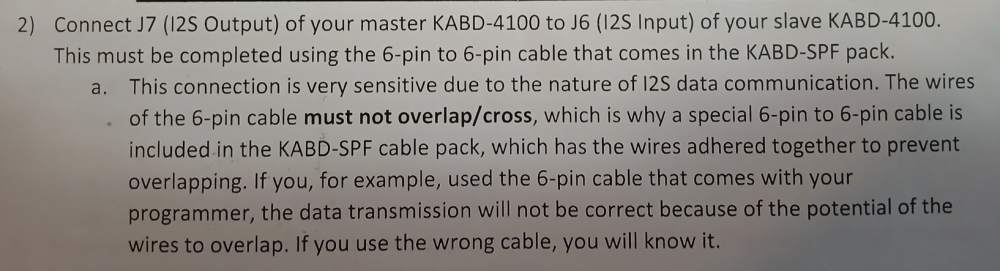
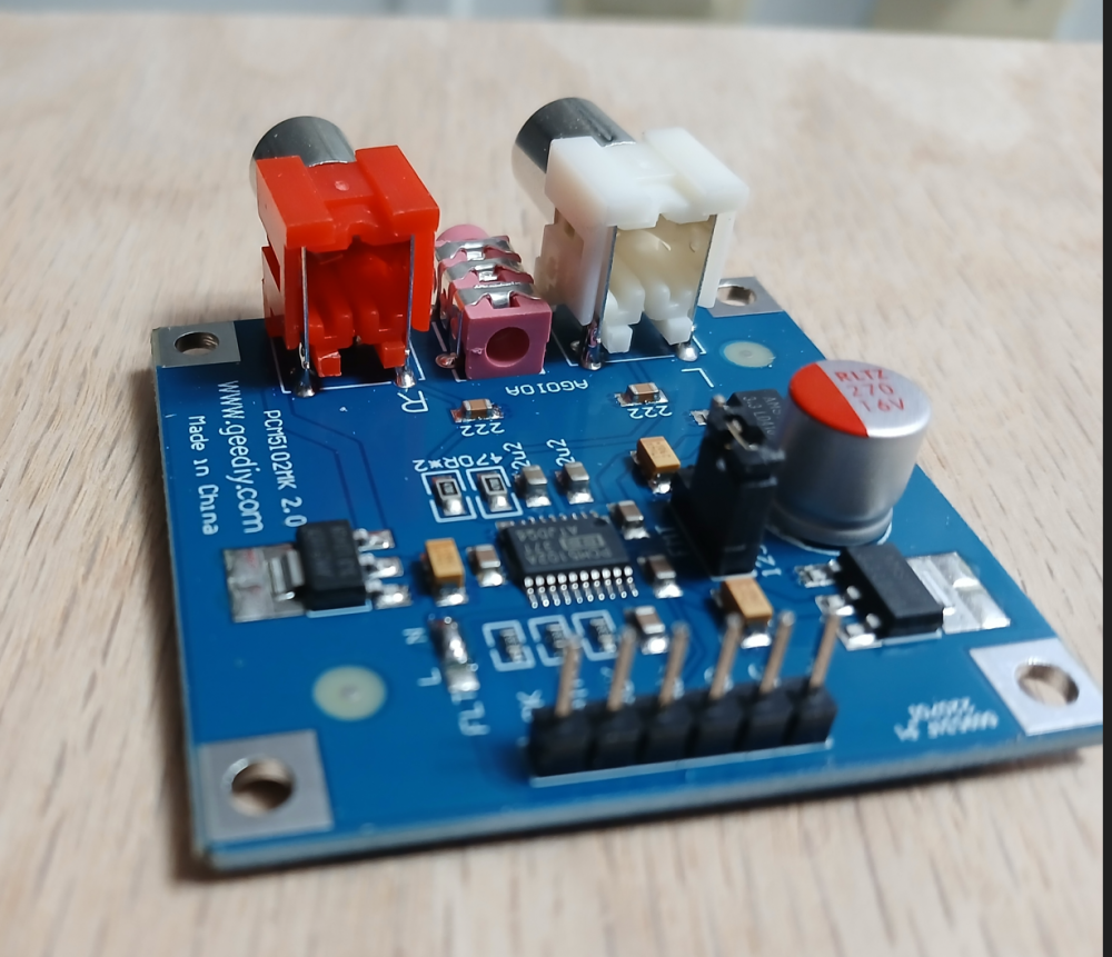
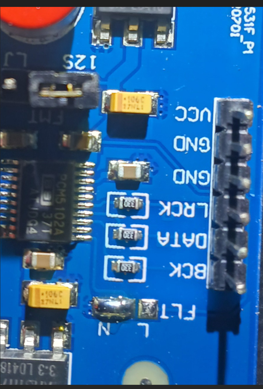
I didnt actually pay attention to what the individual pins were labeled as. My KABD has the pins the same config as the pic you posted. The PCM 5102 however has a different set up or at the very least labels the pins different. See pic
I believe the “must not cross/overlap” is best practice, but not always necessary. I’ve used single jumper wires successfully using that DAC. So, it’s up to you how to proceed.
Modifying the existing cable has the best chance to succeed, but you have the task of attaching the 2.54 mm pitch connector. One plus is you don’t need the MCLK line (the highest frequency signal). I’d clip and remove that line. Worst case it fails and you have to order the KABD-SPF Function Cables from Parts Express for a replacement. You’re out $11 + shipping plus the 2.54 mm connector items.
I personally would first try the jumper wires I linked to. There are multiple vendors (e.g. Adafruit ($6.95), etc.). IMO the main drawback of these jumper wires is their length of about 8". I’d prefer shorter, but couldn’t find any with the 2 mm and 2.54 mm ends. Do clip and remove the MCLK line. Failure means you’re out the cable cost + shipping. And you still have the original cable. Here’s one piece of advice from Adafruit: “For best results, when plugging these in a line, have the sides with the 'silver latch bit' sticking out since that side is a tiny bit wider than 0.1" or .08".”
It's DIY, try whatever you like!
In regards to cable length, I see that all the time on breakout kits/breadboards for embedded systems. The chips are really designed with colocation on a PCB in mind. Data rates and expected signal latency are baked into that assumption. I personally wouldn't worry too much about individual jumpers vs single ribbon cable, just keep the jumpers from looking like spaghetti.
Thanks Ed for your comments in this thread! I'm about to do a similar build using a pro-audio amp to handle subwoofer duties on a 2.1 system.
I ordered the jumper wires. Thanks again for your help without belittling. Rare these days
^ That's exactly why I hang around here - good/helpful/decent/constructive people - and they put up with me . . .
Stick around.