Site Links
Howdy, Stranger!
It looks like you're new here. If you want to get involved, click one of these buttons!
Quick Links
Categories
Who's Online (0)
The LaVoce WSF041.00 is a pain in the tuchus
But I hammered it into shape the best I could.
DX25TG59-04
WSF041.00
DS315-8
This was a commission of sorts. I coached a guy through taking his own measurements via email. By the 4th run, he was getting really good correlation in his data at both 4ft & 6ft, so I had pretty good acoustic offset data.
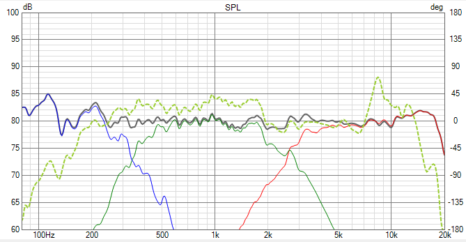
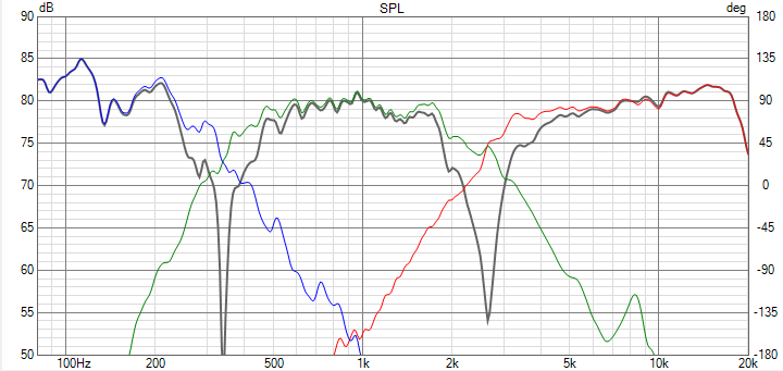
Filters both came out to 4th order acoustic, with crazy nulls. 350hz & 2.6khz. Crossing to the tweeter as low as we do, I'm hoping for pretty good power response. Fingers crossed that it sounds as good as it looks. Haha
Thoughts? Criticisms?
The dashed green trace is the raw midrange response. That 2khz shelf drop-off annoyed me to no end:
NOTE: First reflection @ 220hz.


Comments
Is it necessary that driver spacing be entered in Y axis to get an accurate simulation?
I think the biggest question for a design like this is what the woofer SPL actually is relative to the mid-tweeter. Gated measurements aren't very accurate down at the woofer-mid crossover point and you might get some boundary reinforcement for the woofer depending on its proximity to the floor. I've had 3-way designs like this where I have had to make 1-2 dB adjustments to the entire mid-tweeter target SPL after listening.
Sehlin Sound Solutions
It just seems like without Y coordinates you would be telling the software that the drivers are stacked on top of each other.
Yes, I noticed this too.
IF all measurements were taken on the tweeter axis then zero y-offsets are correct. But, this is NOT the standard that VituixCAD recommends.
I know, I know. I'm probably leaving a whole bunch of features & data views unrealized. But that was exactly the measurement condition for the data shown (from 6'). Perhaps I'll go back and add those axes (convert my delay inputs to distance).
I feel pretty good about the phase coherence. I can add a lot of delay on the mid before things start to fall apart through the crossover region
I've been recently curious about that particular midrange. That shelf seems problematic for sure, but is it any kind of boundary or distance problem, I mean, does it behave itself on larger baffles?
InDIYana Event Website
He measured out of doors, about 6' off the ground. The woofer & mid were gated to ~80hz. The reflection @ 220hz was, I think, from the side of his house as the next closest boundary. We also took nearfield data, but it wasn't a good candidate. The enclosure didn't have the ports installed and there were some funky step response ripples in the near field right where I would have done the splice.
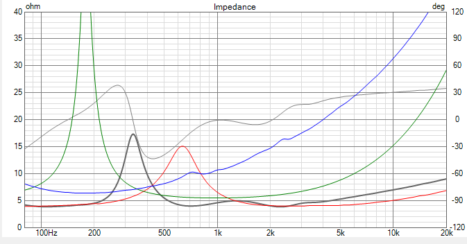
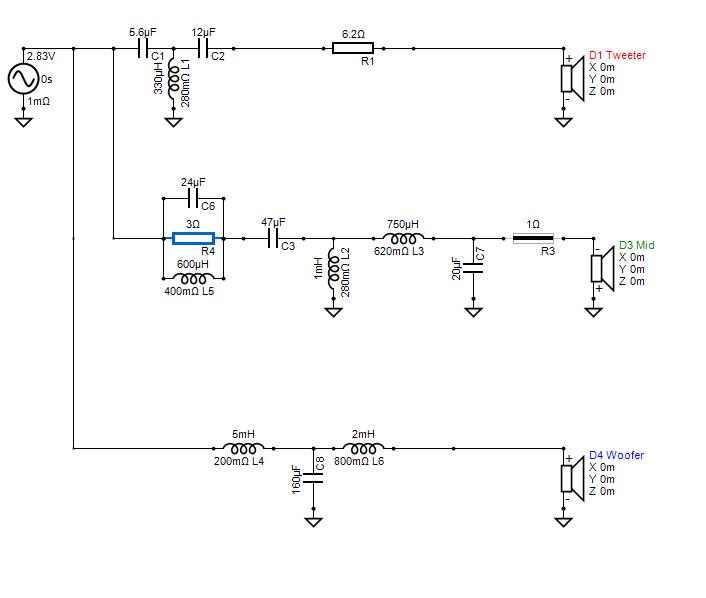
But to your point...this is the one thing that doesn't thrill me. There is presently a zero ohm padding resistor on the mid, and I would really prefer that was more like 2-4 ohm. Before I tell this guy to spend $140 on parts I'd like to give him better options for tunables.
This was a 15W x 24H baffle. Offset from centerline something like 2-3".
One of the reasons I had the guy take yet another round of measurements was because I was hoping the shelf was a boundary problem that might disappear with the mic moved. Nope.
You can see the shelf in the factory graph if you squint real hard. Their smoothing really downplayed it.
Looking at your raw mid vs. the manufacturer's graph and the measurement conditions discussed here, I think your overall mid-tweeter level will be pretty close to what you have now unless the end user is going to set them on the floor or close to room corners, in which case they will be bass-heavy. Given that your mid and woofer have similar sensitivities and the crossover point is 350 Hz, it makes sense that you aren't padding the mid as it's already taking most of the baffle step losses.
The main "tunable" you will be able to suggest is a favorable room placement and/or short stands.
Sehlin Sound Solutions
I want to agree but I am confused. It seems to me that for the software to work correctly it would have to know driver pacing. I get near perfect agreement with my combined measurement when I enter the Y coordinates in before attempting to find Z offset. Triangulation. Sorry, that's just a word I pulled out of some place.
Triangulation is a process used to draw 3 sided shapes.
The triangulation process would not apply to your measurements with OmniMic, since you make all measurements on tweeter axis without moving the microphone. You only need to enter a time delay on Vcad's driver tab. You should be leaving the X,Y,Z coordinates on the crossover tab as zeros.
I want to agree, but
What are they for?
So I input electrical profiles and acoustic profiles that have been derived from a single point. I input the combined response to determine acoustic offset by comparing it to a derived profile. But I do not see how it can be derived without knowing driver spacing CTC
Separation loss
I have an easier time thinking of its inverse. Acoustic coupling. Mutual coupling
And on the higher freq end there are other forces, cancellations that seem to me must be simulated by the software too.
I dont always say things well.
This seems a discussion of how to use tool. A tool that we picked up off the ground.
Entering X/Y/Z data enables the directivity graph. But unless you load a full spin-o-rama's worth of off-axis data, the graph isn't correct. Here's what it showed me:
Which shows that I'd only be -5dB down through the upper mids / lower treble 180 degrees off axis. That's pretty amazing....but it's also not super correct since Vituix doesn't have any driver directivity data to make it an honest graph. 180 degrees off axis, like everything above 1khz should be dropping.
I calculated the Z data using the method Jeff Bagby popularized (and was later added to the Omnimic suite). Measure the mid, measure the tweet, and then take a 3rd measurement with the two drivers in parallel. Take those files, ensure min phase, and load them up in your sim tool. Load that 3rd measurement as overlay, and simulate a mid & tweeter connected straight to the amp. Vary the Z (or time delay) on the mid until the summed response graph matches the overlay. That's your acoustic offset.
I do not change z to find offset. I leave z at zero if the are on a staight baffle, and I change delay ,offset to get a match
Straight is plum
I don't always say things right
X Y Z are physical
Should we take this XYZ discussion to a new thread? I'm concerned that we are hi-jacking Dirk's thread.
Eh, Dirk's gotten what he wants out of it. Scott's comments mirrored my own thoughts.