Site Links
Howdy, Stranger!
It looks like you're new here. If you want to get involved, click one of these buttons!
Quick Links
Categories
In this Discussion
Who's Online (0)
Sound Power Response

As often is the case, Traw posted a thread about a new speaker he is designing and it veered into a side discussion on something else. The side discussion was about Power Response and the variations of bright and dull that was observed even though the on-axis was flat.
@4thtry said:
I'm starting to figure out why this happens. Measures flat on axis, but sounds dull with no air. Measures flat on axis, but sounds bright. Measures flat on axis, but sounds harsh. Measures flat on axis, and sometimes sounds OK. I'm finding that I need to look at the tweeter response as if it is divided into at least three sections. 1) The top octave, 10k to 20k on axis, where most tweeter's start to beam. 2) The mid treble section, 3-7kHz or so, where too much energy makes the entire speaker sound bright and harsh, and 3) the overall power response over these same frequency bands. Flat on axis with a bulging power response in the 3-7kHz area sounds bright and harsh every time. Flat on axis with a drooping power response above 10kHz sounds dull. And all of this is generally due to a directivity mismatch between the tweeter and mid/woofer that needs to be resolved in some way.
There are many people on this forum that design very good sounding speakers using different software and different degrees of measurement. In my particular case, but I think also for many of the people like me that are relatively new or don't have the best "trained" ears, the closer we can get to a good result based on objective measurements as a starting point the more likely we are to getting to a good ending point.
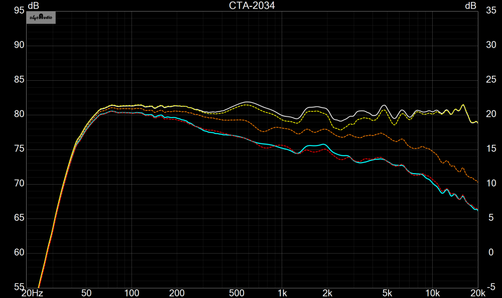
Below are Power Response curves based on different levels of data. Typical Spinorama would call for 0-180 degrees horizontal and vertical in 10 degree increments. 0-90 degrees being okay if symmetrical. Unfortunately, in this case I only had 15 degree increments.
White line is the On-axis SPL of a speaker with xo in place.
Yellow is Sound Power (SP) if ONLY an on-axis measurement is used.
Orange is SP with only 0 to 75 degrees horizontal, in 15 degree increments.
Red is SP with 0-180 degrees horizontal, in 15 degree increments.
Teal is SP with 0-360 degrees, horizontal and vertical, in 15 degree increments.


Comments
OK, I thought that the other thread was a miscellaneous diatribe type thread. Did'nt realize I was hi-jacking. Sorry about that, Traw. I'll move my future power response comments over here. I commented on Wolf's response to JR as follows:
I agree. It's a juggling act requiring you to synchronize several tweeter ranges (3-5k, 7-10k, and 10-20k) to get the mid/tweeter combo to sound right. The key is to find a mid/tweeter combo with a good native directivity match. You either have to narrow the tweeter with a waveguide to match a 4 to 6" diameter mid. Or you have have to widen the mid's directivity by selecting a small midrange driver in the 2 to 3" range.
And my response to Ani moved over:
@ani_101 said:
Can we see some effects of the power response in the office axis measurements, bunching vs spreading and what they sound like?
Yes, you certainly can. The bunching is a concentration of energy and creates a bulge in the power response (or the early reflections power response, if you are looking primarily at the forward facing angles). If this bulge occurs in the 3-5kHz area, then you can get a bright, harsh sound quality that lacks "air" on the top. The loss of air on the top is often caused by the fact that most nonwaveguide tweeters mounted on a flat baffle start to beam above 10kHz. Measures flat on-axis but sounds bright and harsh.
Wogg had a thread over on PETT where 0-90 degree polars verses 0-180 degree polars were compared. I'll see if I can find it and post a link.
Here it is. It was on page 3 of Wogg's Anarchists build log thread: https://techtalk.parts-express.com/forum/tech-talk-forum/1490282-anarchists-build-log/page3
LOL, I may be the one who is wrong. I interpreted that as a name for the speakers he was starting..."The Diatribes" but now that you point it out...hmmm
I plan to do a similar study. I started to...I took measurements of the yellow studio monitors I brought to InDIYana in 5 degree increments...they are a 3-way, and asymmetric, so I had do full 0 to 360... it was about 432 measurements. But my mic started messing up and is now being fixed at the factory. (Ha, maybe I wore it out.)
Anyways, I know it is conventional wisdom that going the extra 100 to 180 degrees isn't THAT important. But it is even more widely accepted that taking the verticals isn't that important. But what I started to find was that taking the verticals, even if in 20 degree increments, mattered more than taking more precise horizontals. For example, taking 0 to 360 degrees in 30 degree increments horizontal AND vertical was better than just taking horizontals 0-360 in 10 degree increments. [As a disclaimer, the differences were quite small.] Unfortunately I have to come back to that when I get my mic back. But I have a feeling it is somewhat dependent on the speaker. I can easily imagine a small, symmetrical 2-way where verticals don't add much, whereas a big 2-way tower they might be more relevant [although still likely small relative to other important factors].
Here is an example of my failed Peerless DA32TX + Esoteric ES180Tia project. Notice the relatively flat on axis response together with the huge, bulging power response from about 3-5kHz. Crossover is 1kHz LR2/4. This bulge, as I see it in retrospect, was a direct result of the huge directivity mismatch between the nonwaveguided tweeter and the relatively large 7" esoteric woofers. See how badly the sound power directivity index and the early reflections directivity index shifts above 1kHz as the woofers hand off to the tweeter. This speaker was a disaster. It sounded bright & harsh with little "air" at the top end. I demo'd these at IowaDIY 2022.
I hope that the power response of a loudspeaker will get more attention because it can influence the "sound" or tonal balance of the speaker more than you realize, and is almost as important as the on-axis response. This is because what you hear when you listen to a speaker in a room is both the direct sound and the contribution of multiple reflections from room surfaces. Each reflection of sound emanating from the speaker in some off-axis direction modifies the tonal balance of the reflected wave through adsorption or transmission loss. This typically means that the room has its own response curve that depends on size and what is in the room (lots of material to adsorb sound or lots of solid bare concrete, etc.).
There is often a problem with the power response in 2-way loudspeakers. On axis a woofer and tweeter can be made to play nice but when the woofer is large or crossover point is high the woofer is probably starting to beam by the time you get to the crossover. Then the tweeter takes over but it will be radiating as a monopole. So the power response has a dip and then jumps back up again. This can be even worse with an MTM. Using a tweeter that is a horn or a large waveguide can really help with this problem because the tweeter will have a directivity closer to the woofer. Choosing the right diameter woofer for the crossover point is also another way to control how the directivity and power response behave through the crossover point. Finally, you can use something like a dipole that has much more constant directivity for all frequencies to flatten/smooth the power response. Note that any old OB design will not necessarily have a dipole type response nor relative constant directivity.
No matter what type of speaker you design, try to achieve a smoothly varying power response and this will help you get more consistent predictable sound in a wider variety of room types and sizes.
+1. Power response, as I see it, does not appear to get enough attention because it is difficult and time consuming to measure. Many builders do not have the equipment or the time. VituixCAD and 360 spin data can make this possible, but lets face it; it takes alot of time and effort to do this properly.
I think what we need to do is take a poll of speaker builders, asking them how they actually measure power response when building a new speaker system. Please let us know what tools you use and how you use them. What are some of the short cuts that can be used to reduce the amount of time needed to make good in room power response measurements? For instance, is it "good enough" to just do some quick 0 to 60 degree measurements with OmniMic, clicking the update average box 6 or 7 times, to produce a rough idea of speaker power response? Or is it "good enough" to use REW's RTA moving mic method to do the same thing? Do you test individual driver directivity, when mounted on your waveguide or flat baffle, to see how well it matches the other drivers you plan to use?
Why does taking off-axis measurements in increasingly smaller increments matter? Why does measuring out to 180 deg. provide any more useful data than measuring out to 90 deg.?
Measurements need to be in sufficiently small enough increments to resolve the differences between the simple, off-axis simulations built into software (ideal disk acting as a piston) versus reality. Power response has been available as far back as PCD and earlier I’m sure.
In the examples posted above, the trends are clear to me in either example.
It seems to me the biggest argument is the still lacking off-axis, diffraction modeling.
I’m a convert and fan of VituixCAD and the CTA-2034 standard, but I fail to understand the need to take 800 measurements.
Cheers,
Yes, but if you apply a correct mathematical formula for power response with inaccurate data then you get an inaccurate power response measure. You have already stated the reason, actual off-axis behavior of drivers does not match simulations well. On-axis behavior typically does though.
Yes, this goes to Bill's point about what is "good enough". Are you okay knowing the"trend" or being within +/-6 dB or do you want to be accurate? There is no "right" answer, it's just a decision for the designer.
A typical two-way with vertically aligned drivers would require: 74 measurements if 10 degree increments, 0 to 180 horizontally and vertically; 10 measurements if 20 degree increments, 0 to 180, horizontal only.
I would argue that power response gets 100% of my attention... when I'm voicing my designs with my ears in my room. Not when when using my eyes to look at a curve on a screen that is generated by an algorithm that uses some "typical" room as the model. For sure that room is not my room, or the Harry Potter room in Grinell, or the conference rooms at Fort Wayne or Ankeny.
This ^ is when/where the light bulb came-on for me too.
I'm currently reading Tool's Sound Reproduction, 3rd Edition, from cover to cover. There are some sections that deal specifically with the "typical" room that was used for his blind listening test sessions. I'll report back with a summary. I've always wondered how this was actually done; but have been unable to find good info on-line regarding specific room dimensions or treatments. There was also an acoustically transparent curtain placed between the listener and speaker, which is another factor to consider.
I think it is unfortunate that they named it "Predicted In-room Response" (PIR). There are basically four measures of off-axis behavior coming out of Toole and Olive's work and Spinorama: Listening Window, Early Reflections, PIR, and Power Response.
They are just mathematical formulas taking into account an increasing number of off-axis angles. But no one ever says "who's reflection" or "who's window" like they do "who's room"? And, ironically, after on-axis linearity, the best predictor of sound preference was PIR, not Power Response.
Power Response is no more "real" than PIR. If I sit in a 6-foot cubed room in my basement or in the middle of a football field, then it is no more accurate than PIR in one real room vs another. They should have just named them: Minor Reflections 1, Minor Reflections 2, Major Reflections 1 and Major Reflections 2.")
Even if its not perfect. It is worth consideration.
I'm just looking to get a discussion going on how seasoned builders approach the off-axis blooming problem when using a nonwaveguided tweeter. Here is another example of one of my recent design failures (measured flat on axis, but sounded bright at Indy 2024). I substituted the Bozhen CQ76B tweeter for the DA32TX by swapping out the top baffle. But again, I got an LR4 type bulging power response caused by the directivity mismatch between woofer and tweeter.
@tktran suggested that I change from LR4 to an asymmetric LR4/LR2 and then move the xover higher (see below). But it had to be discarded as another failure because it caused severe vertical lobing at 2.3kHz (see the eyes, very close to the listening axis).
Could you post your DA32TX LR4 VCAD project? I'd like to play around with it and see if anything good comes out of it.
Kimmo Saunisto on "Proper Design Process":
Here you go, Ed. I zipped up my entire subdirectory for this project, less the large txt impulse files and large DATS files. If you unzip this, you should be able to just double click on any of my *.vxp project files to open them in VituixCAD. All the project referenced frd and zma files should open automatically without error. If you have any problems, let me know. And thanks for taking a look at this. Much appreciated. I am here to learn, so any suggestions are most certainly welcome.
Bill - I sent you a message (I tend to miss them).
Thanks, Ed! Got it.
So I like LR2 slopes and look at 15 degrees off axis as a compromise design axis.
In light of the emphasis on power response off axis, I've been rethinking some of my future projects. Is it true that you can't get "good" (smooth) power response with a MTM design, or can you fix the power response in the crossover?
I tried to ask essentially this same question just a little bit ago, but I don’t think I explained myself well and got limited responses.
In my view, an MTM intentionally skews the power response, but also very intentionally in a specific direction. The resulting power response can end up looking poor. I was inquiring after other’s view on this because I recently reworked the crossover of an early MTMWW I was not happy with. By focusing on the default CTA-2034 standard in VituixCAD I was able to derive something with a much better power response that also sounded good to me, but I dropped the crossover point to about 1.5 kHz if I remember correctly (waveguide loaded tweeter). In this sense, I was avoiding the lobing from the MTM by crossing low. I’ll try to dig up the simulations later if anyone is interested.
Personally, I’ve decided I don’t like directional speakers, so perhaps I was led to this point. I’m still curious other’s opinions on directivity, especially from MTMs. It seems like a mixed bag. Directivity may be worse, but power handling, thermal compression, distortion, etc. are likely all better. Which is more important?
I like the thought that’s been expressed that it depends on whether your room is lively and reflective or dead to determine which directivity response will sound best in your room.
Cheers,
My personal experience with the positive side of highly directive speakers: I get a very "connected" sensation. As if the music is being beamed directly to my ears without the room messing it up. Craig's recent compact line array project gave me that out to the back of the room at Indiy.
Because of that I've been mistified about MTMs too. This link I found recently had some breakthrough info for me (see the last pic): Seems to be very dependent on the crossover. A common mixed order crossover shows to be worse within ~15deg on-axis than farther off-axis (vertical).
https://audiojudgement.com/speaker-lobing-polar-response/
I don't know the answer, but found some interesting posts toward the end of this thread.
https://techtalk.parts-express.com/forum/tech-talk-forum/1411914-mtm-disadvantages
Curious, what if an MTM was wired as a 2.5 way (with bottom M as the .5) ?
Anyone modeled these as comps? Thx
That 2.5way MTM has been done a few times over my time in the hobby. Seems to work well.
InDIYana Event Website
MTM evaluation is ridiculously simple in VituixCAD with any properly measured driver data. Just load data for any midwoofer and tweeter you like, create ideal response with active blocks or G(f) block (use the equalize with G(f) function in the optimizer). Then add second M for symmetrical arrangement and repeat for comparison.
For anyone with some understanding of directivity, it should be clear that the doubling of midwoofers creates narrow directivity in the vertical plane, so power response is reduced, and there will be less reflected energy from floor/ceiling in-room through the midrange. Whether this is beneficial to you or not, you will have to decide.
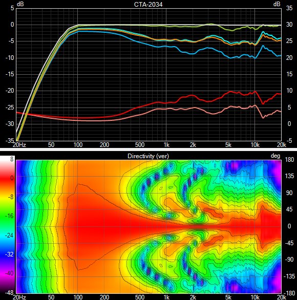
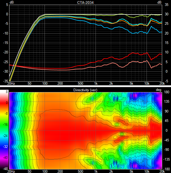
Some random speaker of mine, using a 6" midwoofer, and dome tweeter in a small elliptical waveguide. Horizontal directivity is identical for both, CTA-2034 and vertical directivity plot below.
MT:
MTM: