Site Links
Howdy, Stranger!
It looks like you're new here. If you want to get involved, click one of these buttons!
Quick Links
Categories
In this Discussion
Who's Online (0)
The CR180 Speaker; a fortuitous speaker

I had been wanting to build and replace my own main speakers for sometime now; which are currently a pair of Jeff Bagby's Quarks, paired with a Velodyne CHT8 subwoofer. I never could really decide on a design, or sort out something on my low budget; as I started looking to purchase a house. I especially wanted a pair of speakers to play into the 30s; and not too large as I am in a small apartment currently.
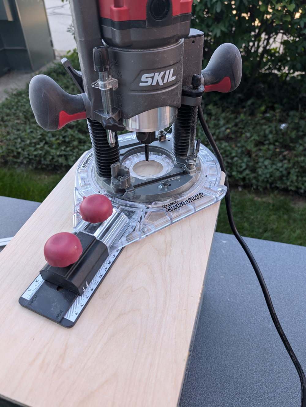
But, as things sometimes go, everything aligned one day! The first bit of luck was the enclosure. Work had a pair of 8in studio monitors that we had helped acoustically tune; and the company didn't want them back. So I had a pair of large, bookshelf speaker enclosures (aprox 1 cuft). After doing some modeling of woofers, I found that the ubiquities RS180P-4 worked excellently in the enclosure volume, tuned to ~40hz with an F3 of 35hz. Coincidentally, the woofer was also on sale at the time. I had a pair of Peerless DX25s laying around, and saw someone else post of how they fit in the Visaton waveguide with ease. The last piece of the puzzle was a router; and one I had been eying popped up on sale (Skil).
So the only major parts I would need to purchase was a small piece of plywood to remake the front and rear of the speaker, and woofers. Was hard to say not to such a deal that met my wants, and the project began! Next post will be the modifying and making of the enclosures.


Comments
Beastmode!
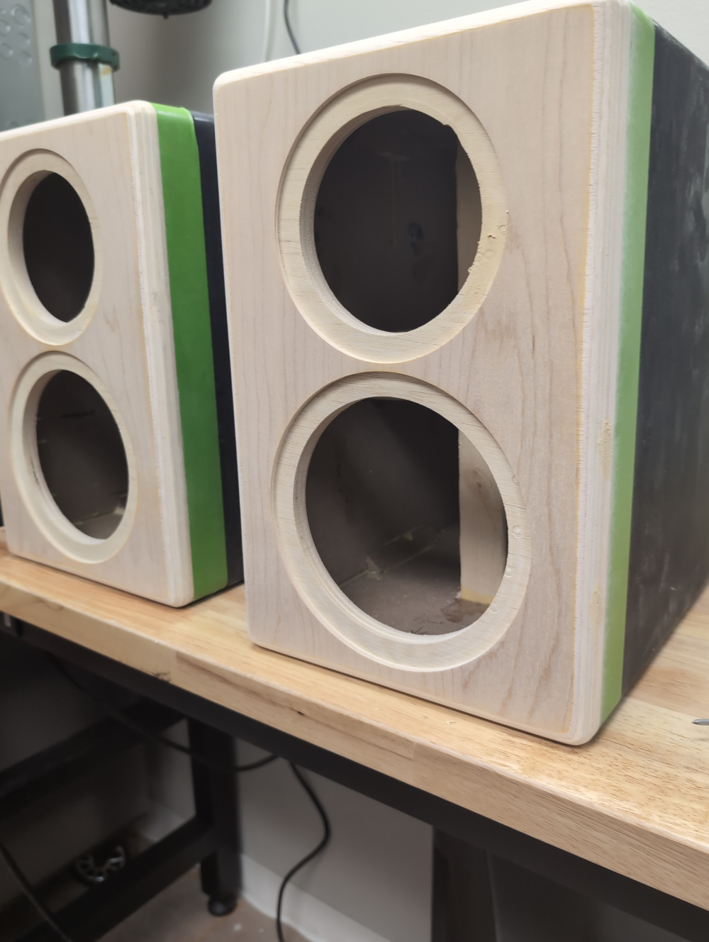
First step was to cut away the front and rear of the enclosure; used a jigsaw to get rid of most of the material, and cleaned it up with a flush cut router bit. Forgot to take pics of this step. Front and back were then replaced with some oak plywood. Rough cut to fit, and flush trimmed. Front was given a 1/2in round over, and rear a 1/4in.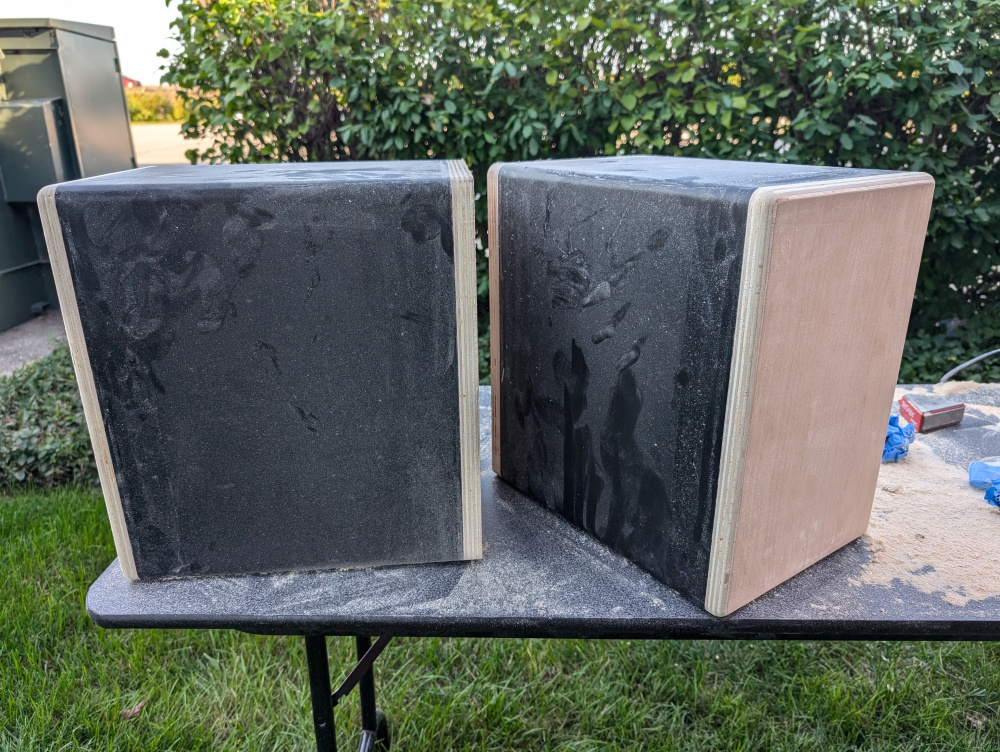
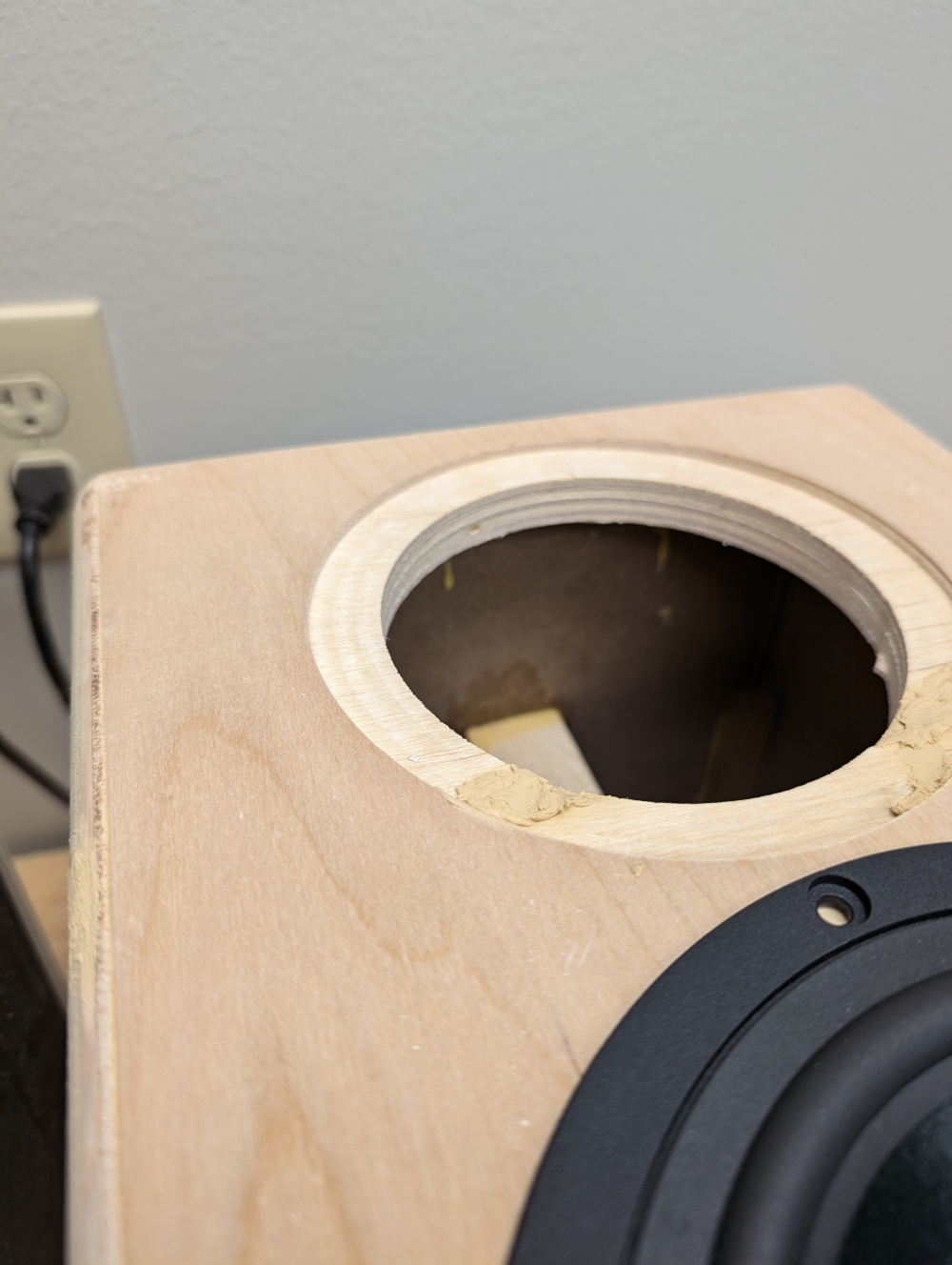
Drive cutouts for the woofer and tweeter/waveguide.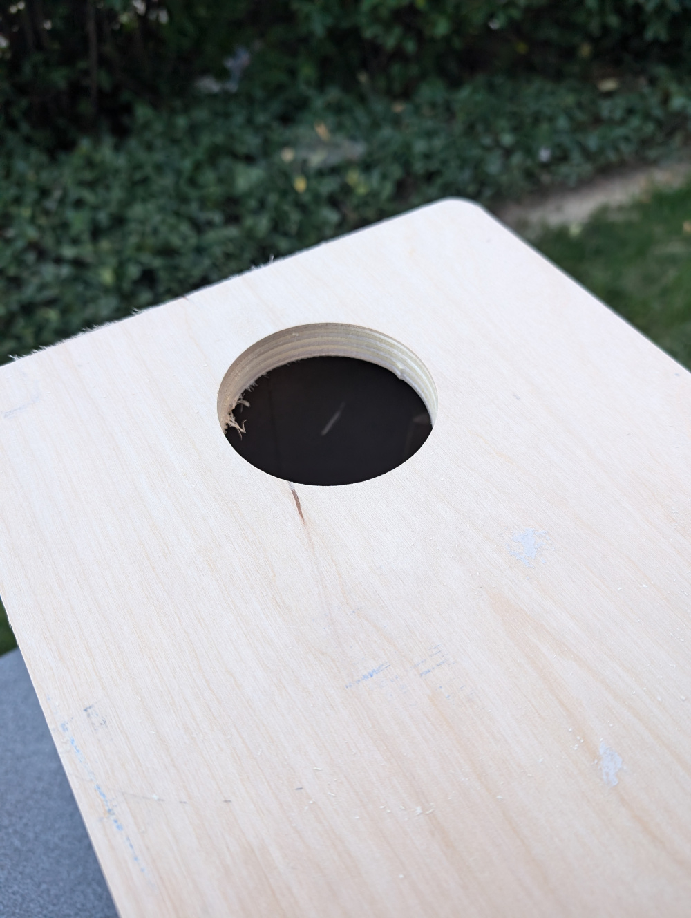
Couple of voids popped up in the plywood, some wood filler took care of that. Overall, things fit fairly well.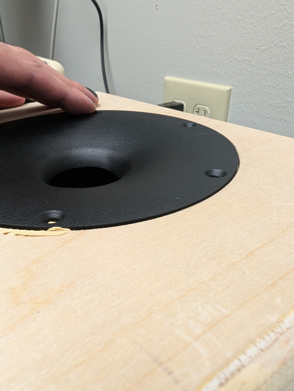
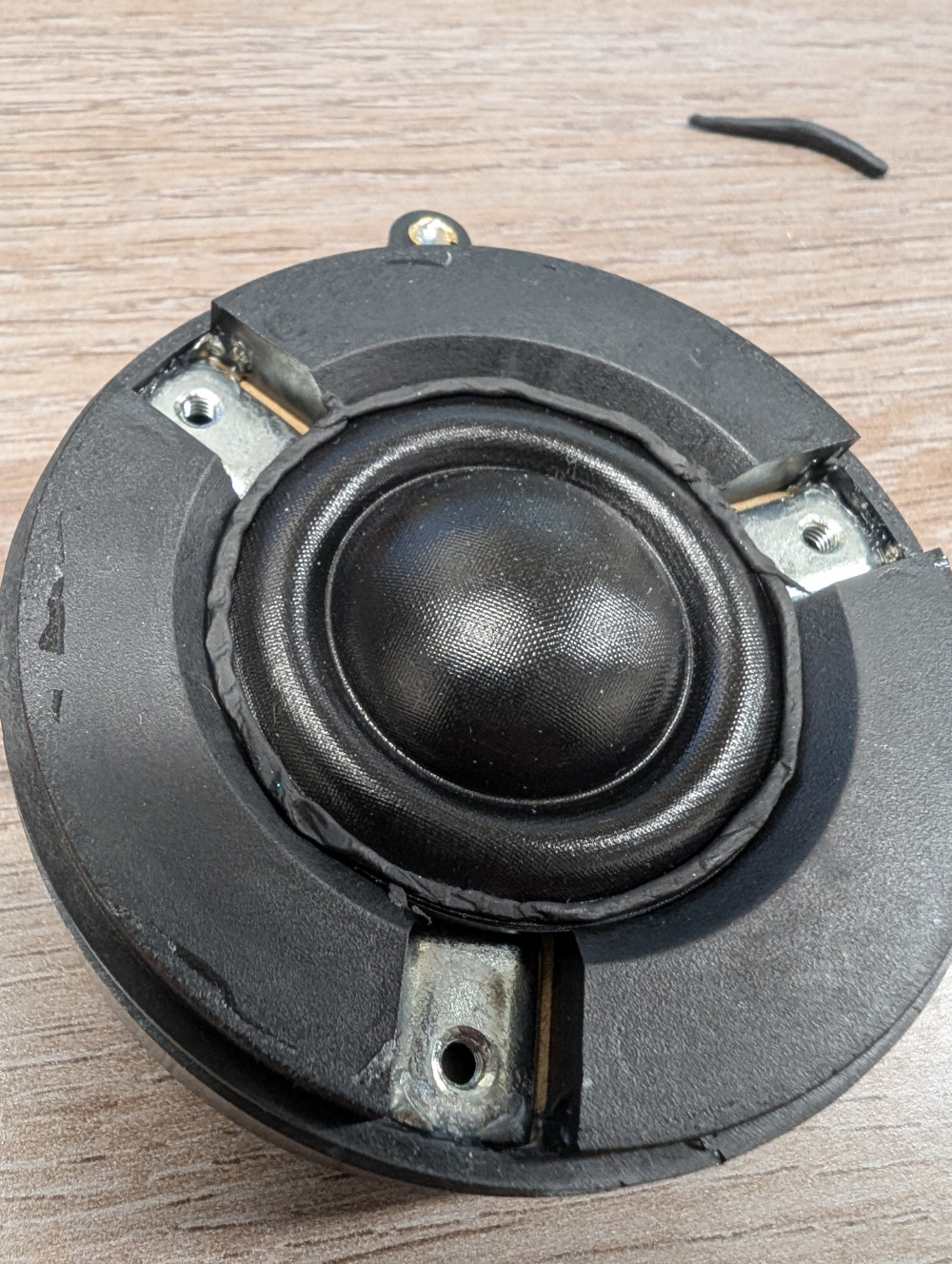
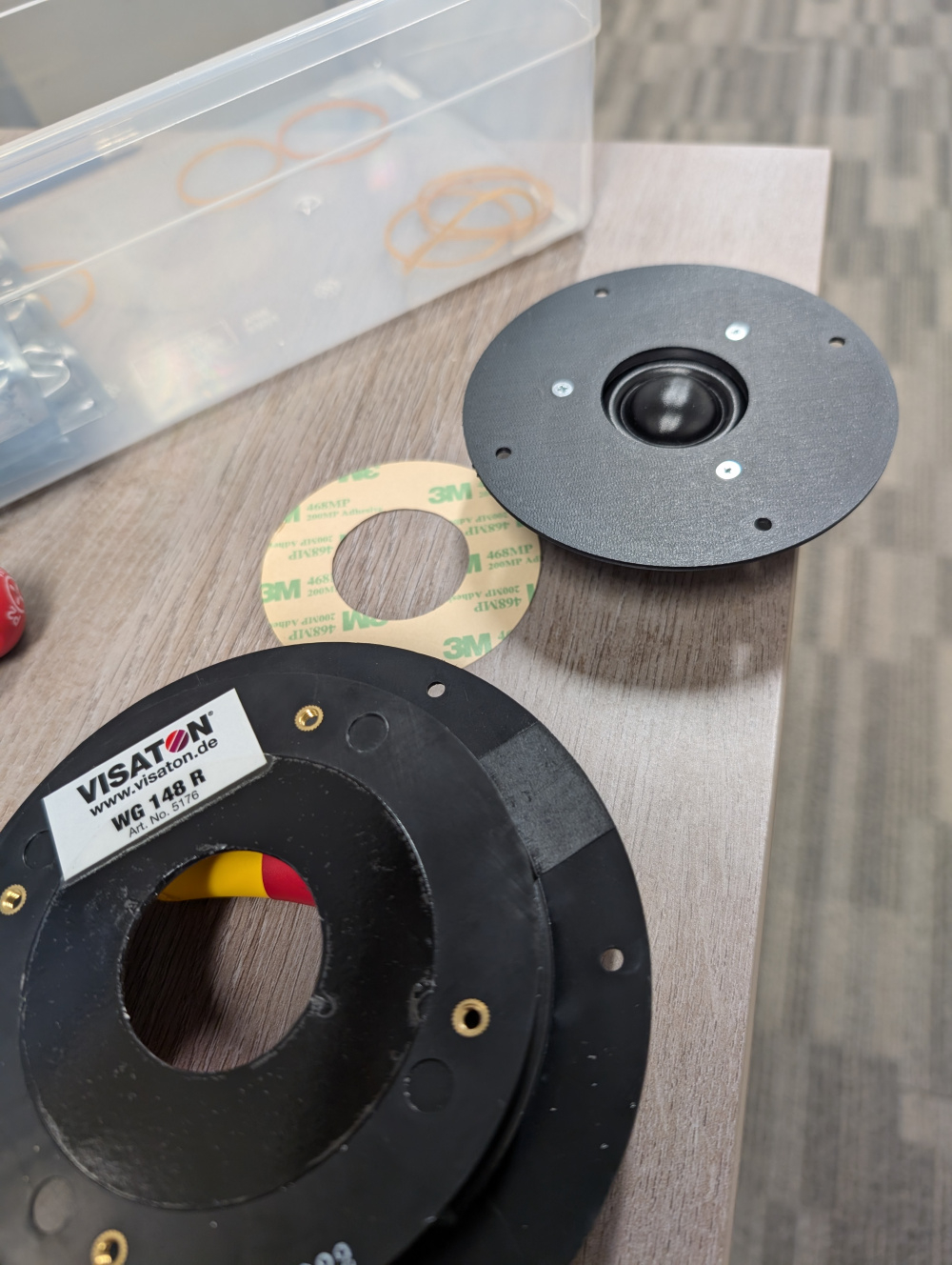
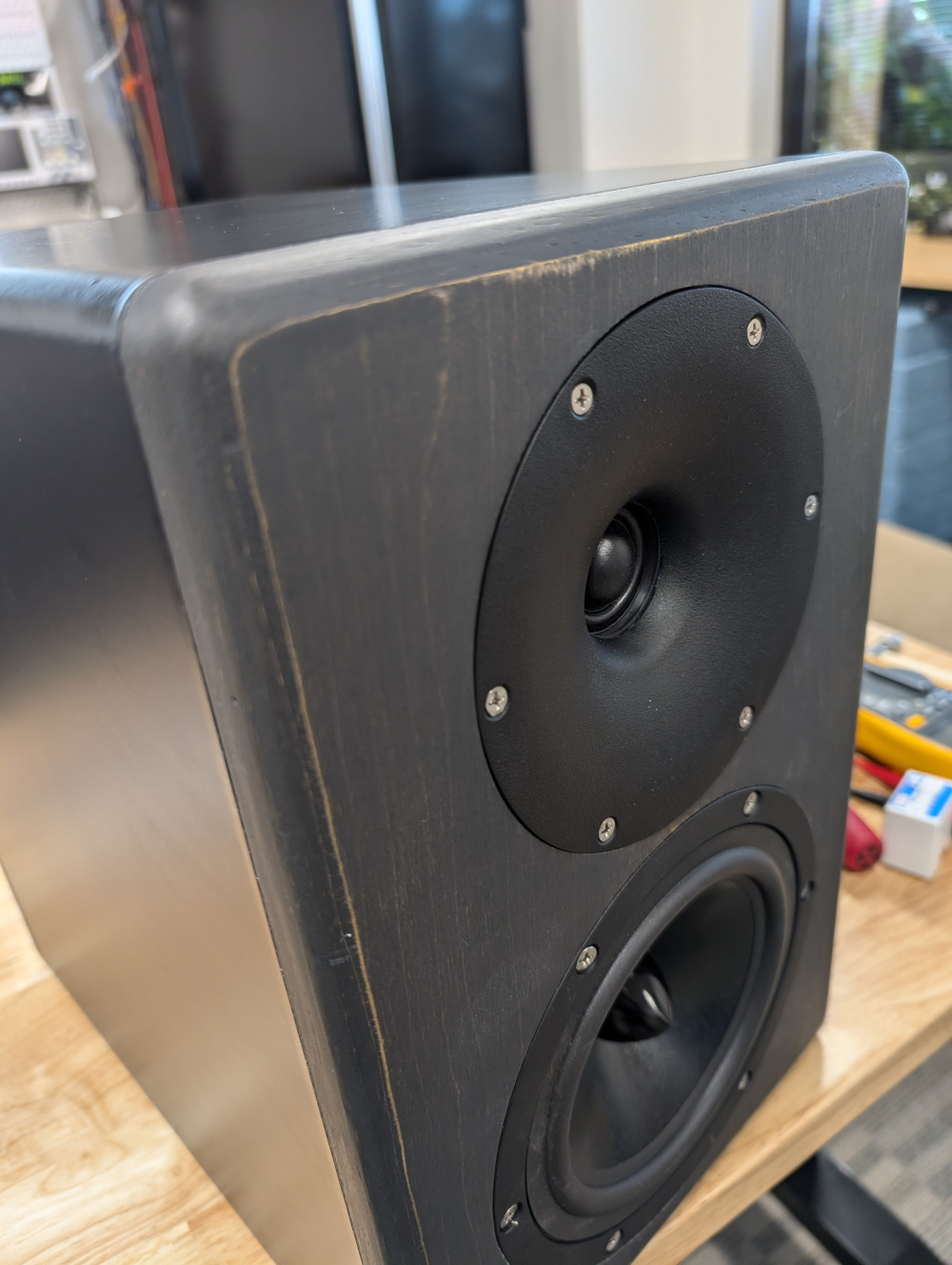
Attaching the tweeter to the waveguide was next. Removed the front plate of the tweeter was quite easy, 3 screws, and some careful prying. I designed and 3D printed a mating plate to the tweeter to the waveguide out of ASA. Was attatched together with some 3M double coated adhesive tape; cut to size on a Cricut. A bit of speaker caulk around the tweeter dome ensured everything was sealed properly. I can post the STL file of the adapter bracket if anyone would like.
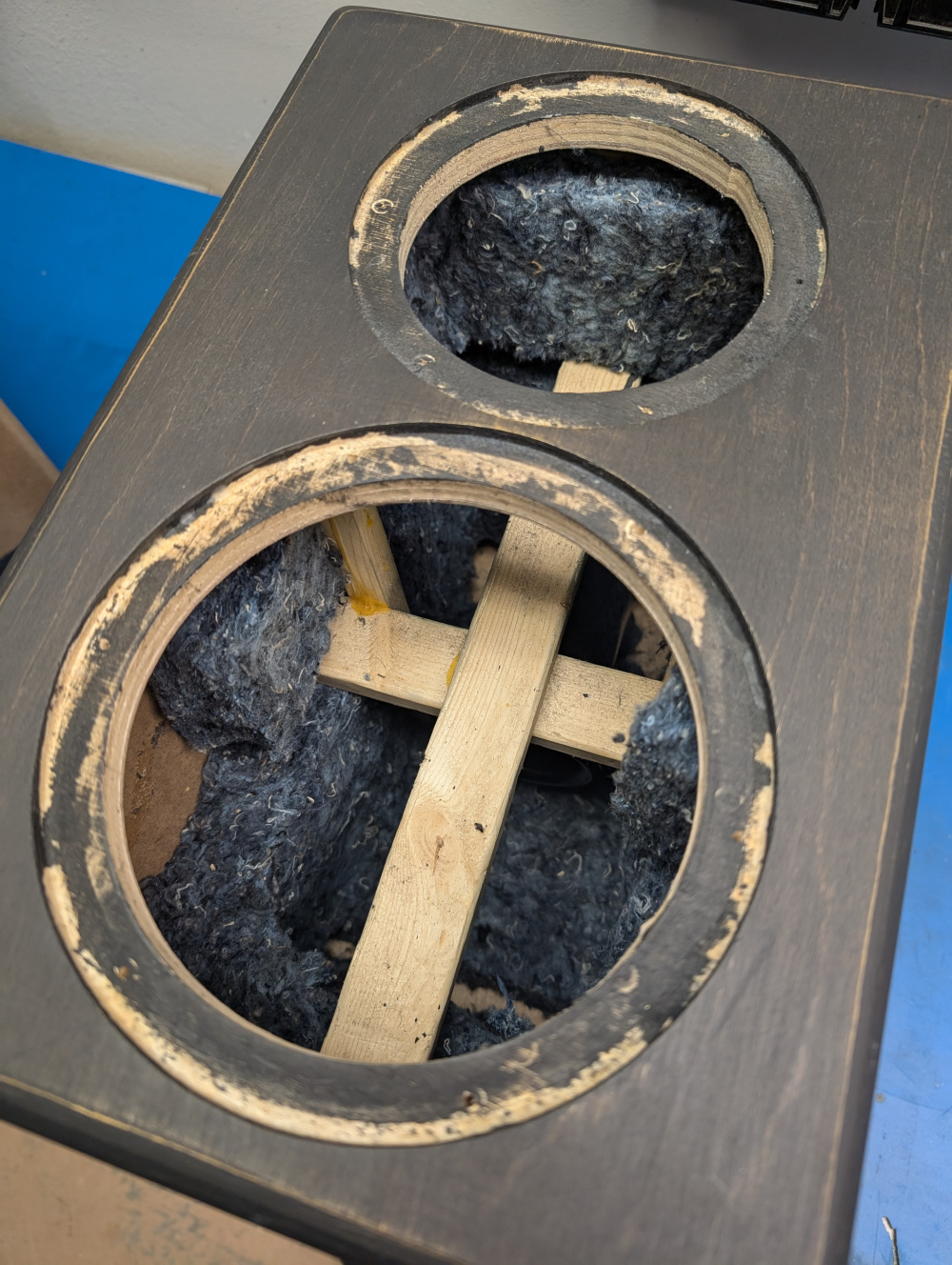
The original enclosures are made of 1/2in MDF, and had no internal bracing. Some light polyfill stuffing was in there, but probably not enough. I added bracing before attaching the front baffle. A cross brace horizontal and vertical, and some smaller braces from the front to the back.Some denim acoustic lined the enclosure.
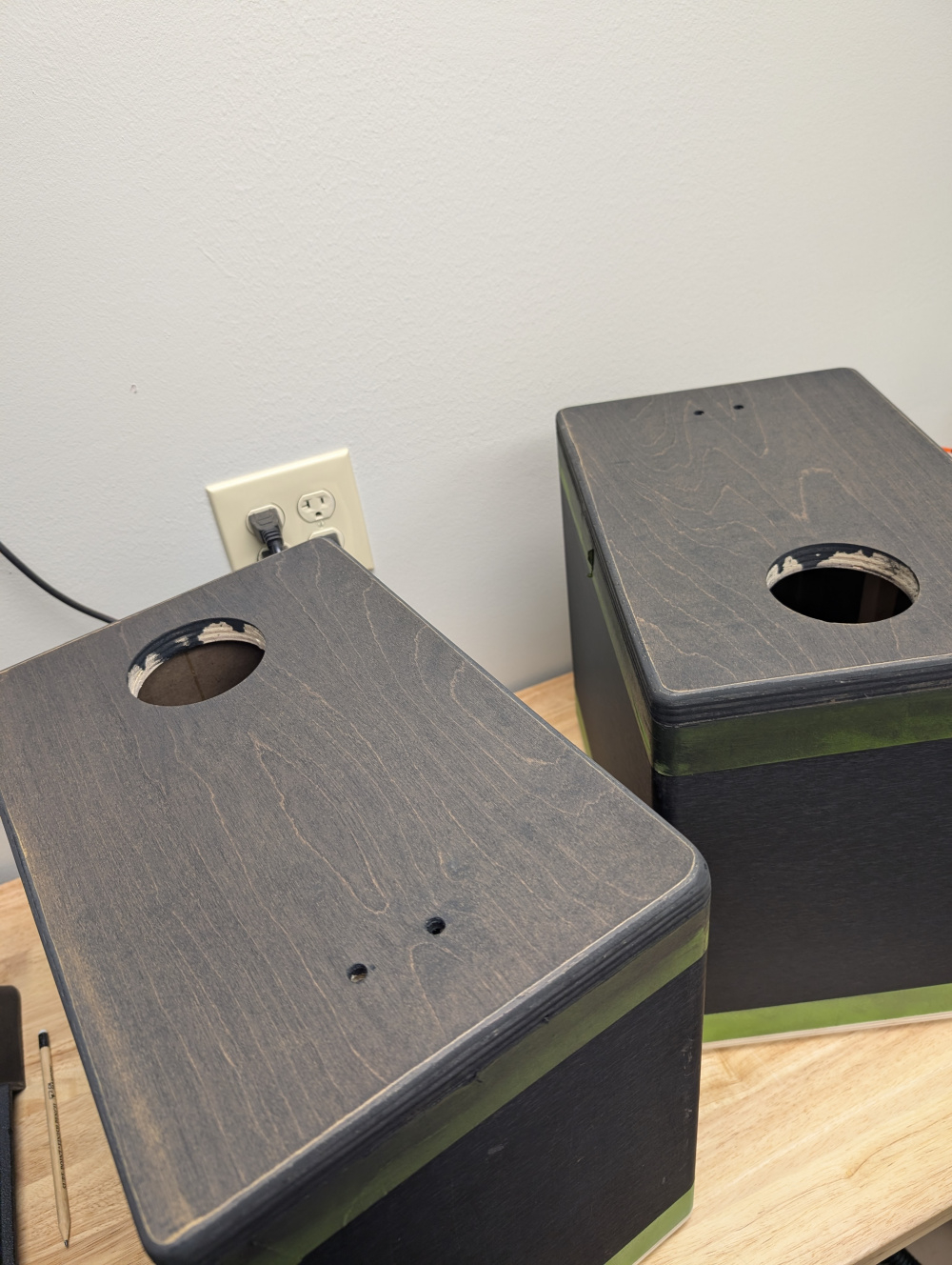
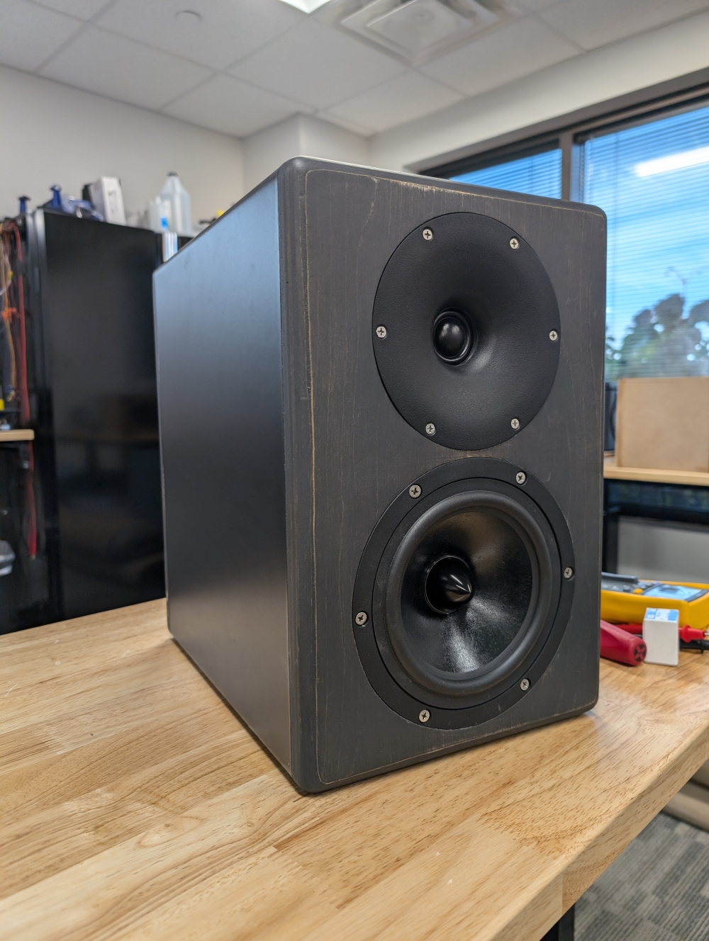
For the finish, I wanted a black color; that allowed some grain to show through. Originally I used a carbon grey danish oil by Watco, but didn't find it dark enough. Ended up changing to General Finishes Graphite water based stain, with their flat out flat topcoat. Quite liked how it turned out! I originally intended to keep the original black vinyl wrap on the speaker, but didn't protect it well enough during all the work. It got quite dinged up and scratched. Simply removed it and replaced it with another vinyl in matte black. I slightly sanded through the oak veneer as it goes; but wasn't too upset with the overall look and aesthetic. Adds some contrast. Finished with stainless steel screws. Up next is measurements and crossover design.
Measuring and crossover time! I built these speakers before I had finished making an automated off axis sequence, so my measurements were somewhat limited. On and off axis to 90 degrees horizontal, in 10 degree increments. Didn't take vertical measurements. At some point, I'd like to remeasure the final speakers to get a full CTA2034 measurement and calculations.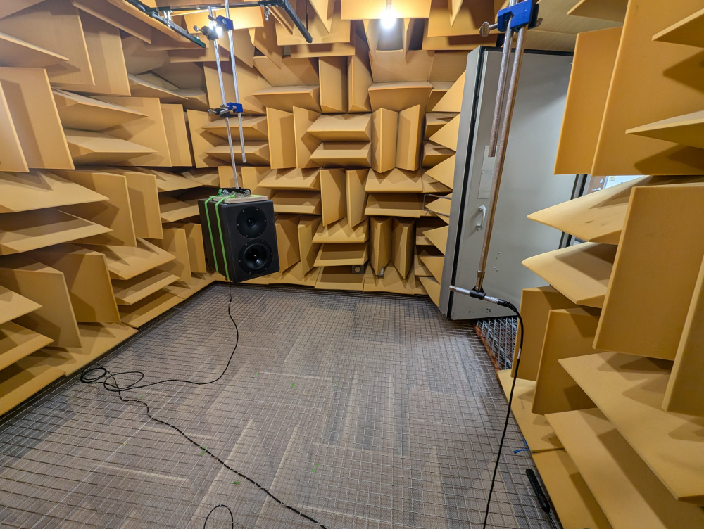
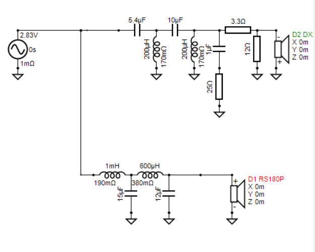
Crossover took a bit of time to sort out. Tried quite a few iterations, but settled on a fourth order; with some padding on the tweeter. A few wiggles up high in the frequency range from the waveguide. I concentrated more so on the sound power DI and listening window; tried to not overthink the on axis linearity as much. Crossover point as 2,200hz, higher than I planned, but everything looked fairly nice. Pushing it lower seemed to cause more issues around 2-3k. Only a mild directivty dip at 2k.The 300hz dip is a measurement artifact; as our chamber is accurate down to around 80hz. Note tweeter is inverted.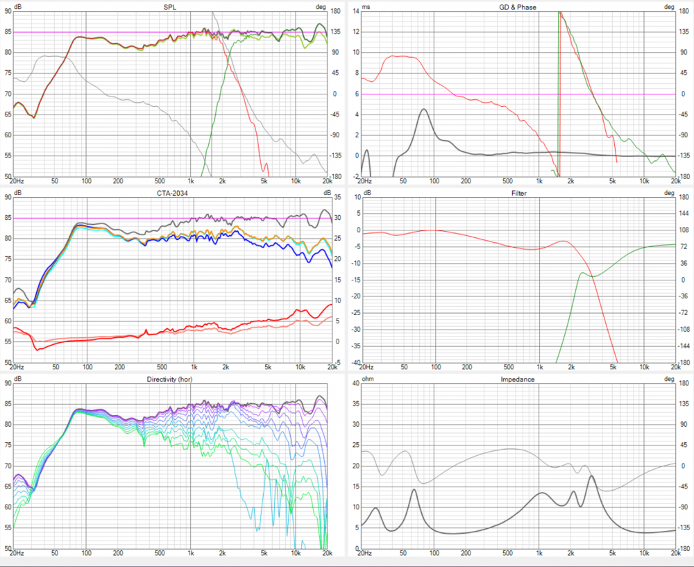
Port tuning was spot on at 40hz. Used one of the new curved ports from PE.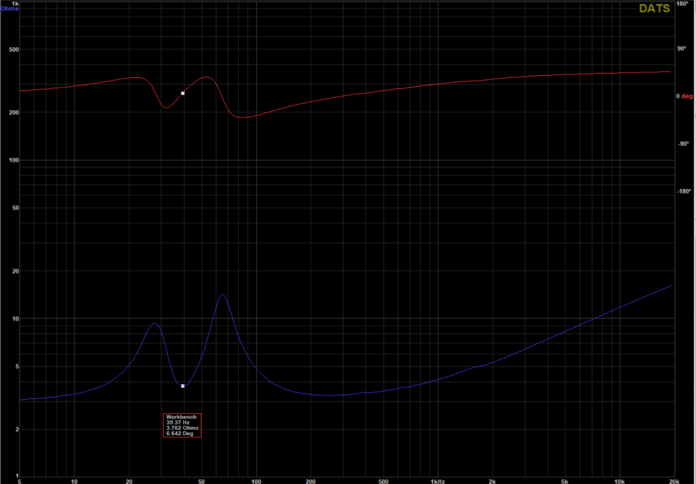
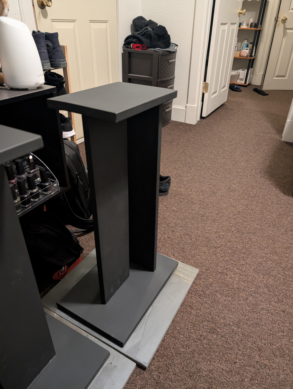
Final (current) place. Will be buying a house and moving in a few weeks; and they'll have some more room soon! Powered by an ICEpower amp in a ghent audio case; from a raspberry pi music server running moode audio out to a Khadas Toneboard DAC.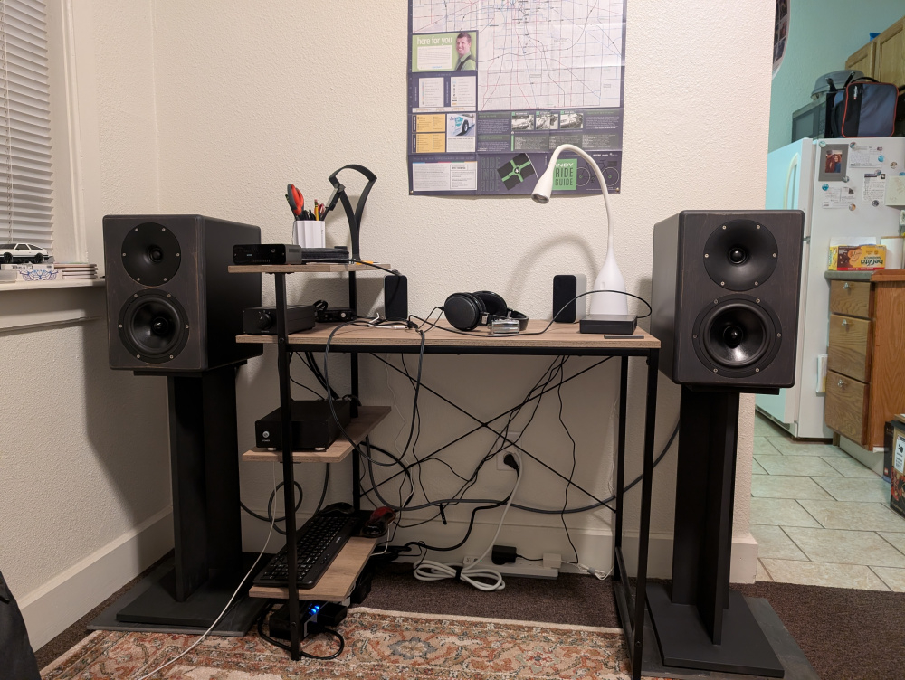
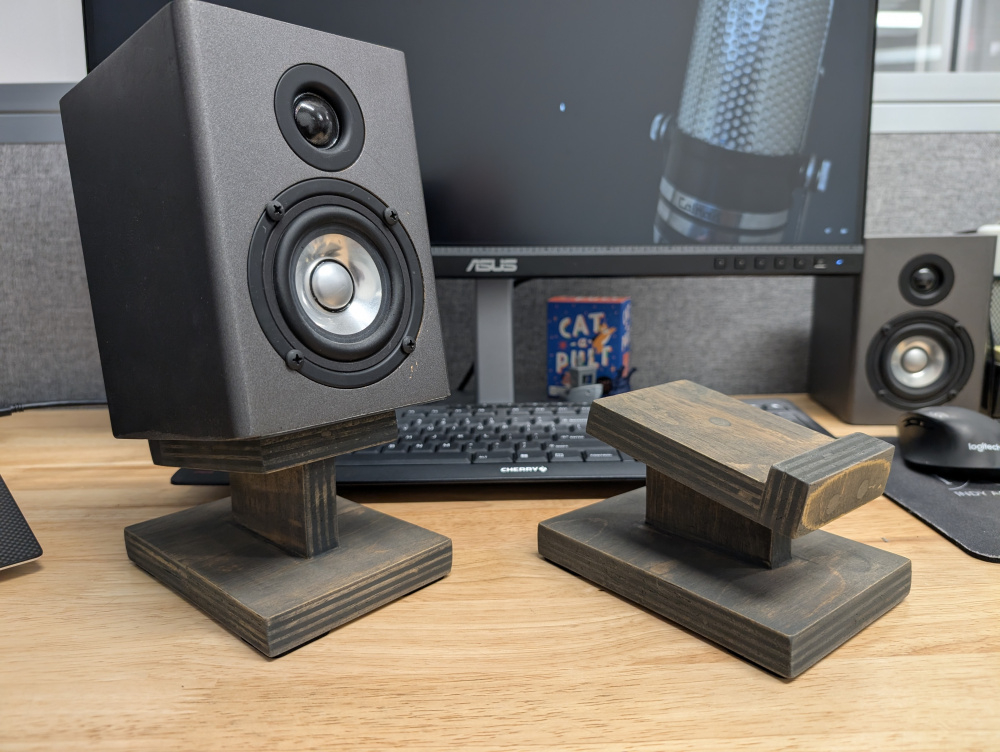
And some bonus content! Used some scrap wood from the front baffle to make lil speaker stands for the JB Quarks; they will now become my work desktop speakers. Finished with Watco Grey Carbon Danish OIl.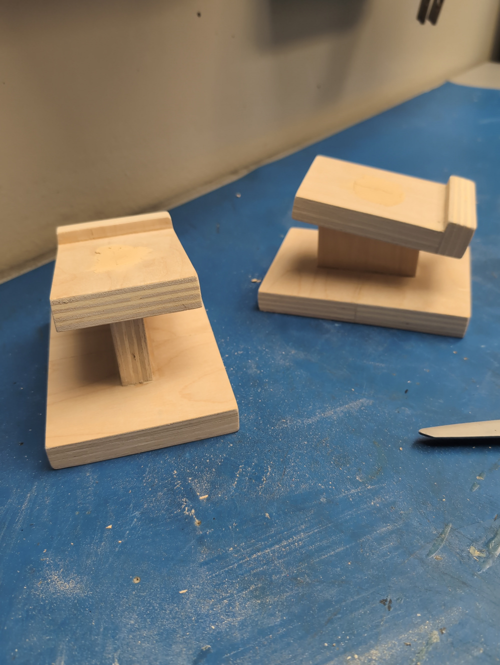
The speaker stands I also made. Bought some preprimed pine panels from Menards. Ended up being more of a paint than just plain wood; the primer coating kind of "gripped" the shoe of the circular saw when cutting, making it hard to smoothly move and cut. The panels also ended up quite warped.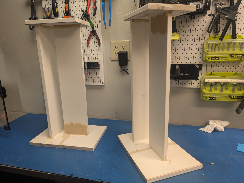
Still, I made it work. Assembled with some pocket screws and glue. Spray painted with Behr Classic Noir Chaulk spray paint, and finished with Real Milk Paint Wood Wax. I originally was going to use milk paint on them, but couldn't get it smooth enough to apply when mixing. Also added some slate tile bases for weight. Attached with construction adhesive, and added some felt pads on the bottom.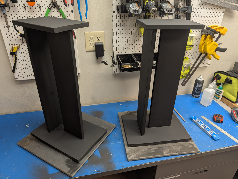
Nice project and detailed write up. Could you explain a little further as to what causes the 300hz dip measurement artifact in the anechoic chamber? Is this created by the dimensions of the chamber, the position of the mic and speaker within the chamber, or something else?
Sorry, I should have clarified and separated those statements. The 300hz dip is from me setting up the speaker height in VituixCAD software; it was the calculated floor bounce. The anechoic chamber is good to 80hz or so (ish, depending on the exact placement of the speaker in the chamber).
So the 300hz dip is "real", in an in-room setting. The raw frequency response of the woofer (below) from the chamber shows no dip, and the modeled room response I used in VituixCAD does.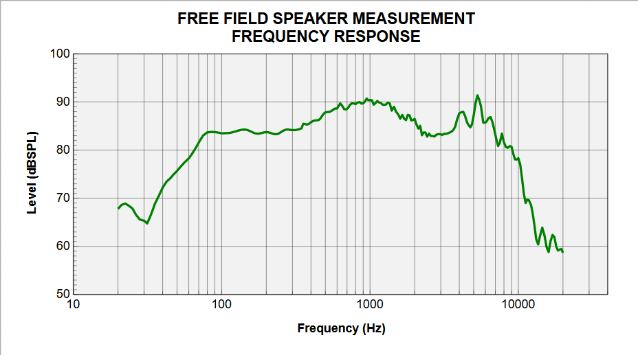
A full anechoic chamber, I’m jealous! The one I have easy access to doesn’t have a suspended mesh floor. Instead you have to play a game like those sliding tile puzzles to move the absorption foam on the floor and it’s only good to a theoretical 200 Hz.
I like the vertical hanging supports for mic and speaker, I think I’ll copy that in my detached garage!
Gotta setup the speakers first thing in the new house!
We have a full grid system suspended from the ceiling, allows for easy movement and placement of the hanging rods anywhere.
Not to increase any jealousy, but the center rod is actually connected to an automated turntable on top of the chamber; allowing for easy off axis and polar measurements.
Rub it in, Duck!
Wow! That is quite the system. A full 360 spinorama should be a piece of cake.
Thanks much for the detailed description on the 300Hz dip. That's an important point. Even with the ability to get anechoic data down to 80Hz, you still have to account for what the room (floor) is going to do.
We use Unistrut in the chamber for hanging rods etc. Quite useful.
You are absolutely right! For the CTA2034 measurements, we actually use a turntable on the floor. Large speakers are difficult to hang off the ceiling rod; especially as we need the speaker offset to rotate on the correct axis. Ends up bending the rod some. All the calculations for the CTA2034 parameters are also calculated in the sequence, requiring no post processing of the data. But, as you said, can't account for the room interaction fully.