Site Links
Howdy, Stranger!
It looks like you're new here. If you want to get involved, click one of these buttons!
Quick Links
Categories
Who's Online (0)
Do slopes matter
This is a breakout discussion from another thread.
Wolf brought up that in the past there have been spirited discussions over whether adherence to prescribed slopes matter. For instance, what is the effect of asymmetrical slopes to the overall speaker where the woofer slope deviates, or the tweeter slopes deviates from the target function.
I might argue that all that matters is the final FR, both on axis and off (and perhaps the impulse response?) Although VituixCad has not necessarily deepend our understanding of off axis behavior, it has brought widespread attention to and acceptance of capturing these measurements in more detail, and paying attention to them! rather than just barely looking at an estimated power response calculated through assumptions related to pistonic behavior.
I might argue these points, but I am also merely a student of audio.
Another example might be the importance of a wide and deep reverse null, versus a smooth power response. I feel like the importance of a wide and deep reverse null in LR2 and LR4 topology was a simplified method of optimization. If you are uncertain if you have the correct measured phase or offset calculated properly, finding a deep reverse null can be a easy tool for confirmation. However, a topology with a shallower null may have a more favorable overall dispersion pattern (polar response).
There I’ve done it! Tear my arguments apart! Or take this in a totally different direction!
Cheers,


Comments
What matter is how the responses of the drivers in the multi-way system add, or sum, on axis where the listener is located (and elsewhere too, but let's keep it simple). It turns out that the slope of the acoustic response (combined effect of driver response and filter response) determines the phase response. It is the phase that in turn determines whether two acoustic waves add together and produce a higher level, or cancel to some degree. So the slopes and therefore the phase responses will influence the frequency response, which is what we as designers want to control.
So, yes, the slope and the acoustic response of each driver is very important.
It's true that you do not necessarily need slopes to be identical, or the same order, etc. But this is typically only because by doing so you still are making or allowing the phase responses of each source to add correctly.
The reason this thread spun off was because of my comment from before, reposted below....
"At one point there was a LONG and somewhat heated another forum discussion between Feyz, Bagby, JKim, and I think DDF, about asymmetrical alignments, their relation of phase behavior, preservation of the transients through both options, and what was truer to form as a result.
Not to place whom was on either side of the discussion at this time, but the previously accepted approach was higher order on the tweeter was the better method. After the discussion boiled down, the other method with the woofer having the higher order slope was for; one designer now a acceptable where not prior, for the second still less than the other for a reason or two, the third still saw no difference between them, and the fourth was still unswayed not liking it at all.
I saw the point of not really mattering in terms of method to be okay with me via the 'on paper' results shown, however, I understood there was a chance in some cases that a phase shift as described would cause a slight misalignment and not completely preserve the transient result in these cases. That said, I have also used this method several times and noted not being able to tell or care that the transient case was ruined or completely preserved.
It's effectively 99% of the time, IMO, a wash either way."
I may have to dig a bit, just to see if I can find it, but I will make the attempt. No promises. I feel it was likely PETT, only because Jkim was involved.
InDIYana Event Website
I think I found (part of) it. Feyz is not in this discussion...
https://techtalk.parts-express.com/forum/tech-talk-forum/21660-lr2-experiment-with-delay-network-for-8945p-810921-pic?t=203023
Also relevant...
https://techtalk.parts-express.com/forum/tech-talk-forum/20885-asymmetrical-filters-and-flat-summation#post269133
Revisited, referencing the previous thread which is likely the one i want...
https://techtalk.parts-express.com/forum/tech-talk-forum/24242-offsets-asymmetrical-slopes-and-mysticism-revisited-pics
It seems like the exchanges I refer to were sometime between Feb and June of '09. Lots of images have disappeared because Jay had a Geocities account, and they no longer exist.
InDIYana Event Website
Thanks for digging this up, Wolf. Much appreciated.
Yes, finding all those took work!
It’s good to read them again (I even posted and said thanks in one of them, lol).
Time and experience lends them different light and insights.
I certainly have no vested interest in, and took quite some convincing to get behind it, but being practiced with and using VituixCad would have settled some of these debates much quicker. No disrespect to Jeff whose software I learned on, but so much of the intellectual exchange was math and theory because we didn’t have as good a simulator and as prevalent the measurements that we do now.
Also this topic reminded me of this thread, which I also think is good:
https://techtalk.parts-express.com/forum/tech-talk-forum/1474680-on-shouty-midranges-off-axis-flares-and-speaker-design
Back on a real topic, I just purchased an RSS390HO-4 and I’m psyched to design an enclosure for it tomorrow.
Cheers,
I think some of this is terminology. When we talk about "slopes" we are often talking about ideal curves that were mathematically derived by people with now famous names, e.g., Butterworth, Linkwitz-Riley, etc. Additionally the roll-off of those slopes, 6dB, 12, dB, 18dB per octave. While we may (or may not) arrive at an initial simulation based on specific named-slopes, with software and actual measurements those "slopes" don't really matter. Consider the fact that almost everyone that starts with a sim then listens and tweaks, so even if you were at LR2 on the both the mid and tweeter, as soon as you "voice" the speaker you aren't at those anymore anyways.
Charlie points out that the slopes (more realistically "shapes" in my opinion) of the curves matter because they effect phase and the acoustic response. Its just that you don't actually need 3rd order Butterworth filters to get a specific end result if using a good simulation. I have seen people make your argument that all you really need is the final FR, both on and off axis. But this not correct. I can load everything into VituixCAD and use the Optimizer and get the flattest on-axis, or the best fit for a target Predicted In-room Response or Sound Power. But this ignores the Fs of the tweeter, cone breakup, harmonic distortion, etc. So there is still art to the science.
And spinorama (specifically ANSI/CEA-2034-A) has been out since 2015 and the work of Floyd Toole, Sean Olive, and Harmon have been known for a lot longer than that (Toole brough a lot of his ideas to Harmon in 1991!). Its just that VituixCAD provides a way to incorporate this into our simulations if we choose to use it - for FREE as DIYers. But of course, many people have known the key issues. Just because someone uses PCD doesn't mean they don't take some off-axis measurements. And when it comes to voicing, people aren't just sitting on a stool one meter away on axis and thinking they are done. They are sitting and standing, and walking to the left and the right, etc. But for those without that experience or well trained listening skills, the additional information provided by the "six pack" of spinorama is incredibly useful.
Spinorama as a process, and VituixCAD as a way to present the data, has been a great addition to the toolkit available for speaker building but unfortunately can me misused. (Kind of like the simple optimizer example above.) So many of the posts on ASR seem to ignore all of the caveats that need to be taken into account. If it measures like "x" it is "good" or "trash", etc. But just like every forum, you have to figure out how to decipher what is useful and not. One thing I find useful at ASR is that Floyd Toole, Kimmo, Lars Irisbo (of Purifi) and some others post there and their posts are almost always very informative. Floyd Toole has practically pleaded with people to stop worrying about the "Preference Score". But the entire ranking of speakers on spinorma.org is by the "Tonality" score - which is the Preference Score.
Yes! And if you aren't using LR2 or LR4 you are unlikely to get the deep reverse null anyways. But with spinorama measurements you can see the important effects of phase that Charlie talks about. I have designed a crossover in VItuixCAD such that the on-axis barely moves when I switch the polarity of tweeter. And I wondered - is one "right" and one "wrong" since I don't see any material difference. But if I have the Line Chart selected in the Directivity pane, it turns out all of those off-axis curves shift too and it is usually quite clear which one is right or wrong. There are also several views of the vertical directivity in VituixCAD, and all of those phase differences (due to changing the slopes/shapes) that Charlie mentioned show up there. If you have perfect symmetrical LR4 slopes, then your phase and vertical directivity are probably good. But what if you tweak it to get a better on-axis response, or tweak it after listening and voicing? If you have really good ears and design skills, then who cares, stick with what sounds best. But if not, more and better information is always better.
Good discussion and points. I'd like to throw in my "2 cents" if I may. I've noticed the comment in many threads about the importance of getting a deep reverse null when developing 4th order LR acoustical slopes. Assuming ideal LR4 target curves and assuming drivers with perfectly flat FR well above and below the xover point, this deep reverse null is achieved by getting the phase curves of both drivers to perfectly overlap well above and below the xover region. But what happens when you do NOT have perfectly overlapping phase curves. In other works, you "cross the streams" so to speak. This can cause the main vertical lobe to tilt up or down instead of projecting straight foward. If your drivers are spaced too far apart, this may cause the main vertical lobe to develop a "pointy" looking peak as well. Combine these two problems and you may hear a shift in tonal balance between a seated and standing listening position.
Then take the example of odd order xovers, either 1st or 3rd order BW acoustical slopes. In this case, the phase tracking will be parallel and offset by either 90 or ~~180 degrees~~ EDIT: Correction: 90 or 270 degrees. The main vertical lobe will either tilt up or down depending on whether the two drivers are connected in or out of phase. And you will not have a reverse null at all.
Regardless of what you do, the various VituixCAD screens will show you what is happening to the vertical lobes as you tweak around. I like to use the single frequency slice vertical polar chart to double check my work. Others may like to use the vertical polar heat map to see what the "eyes" are doing near the xover frequency. I find that VituixCAD is a nice tool to just randomly click around through the various graphs and learn by doing. And I can clearly hear the effects of the vertical lobe shifting around when I mess things up.
Here is a link to the small LR2 verses LR4 power response comparison that was done by Roman Bednarek. This comparison study was mentioned several times in the first thread link that was posted by Wolf above. However, none of the thread's participants provided a link to this study (at least that I could find). So, here it is:
https://www.rjbaudio.com/Audiofiles/LR power response.html
While I’m a ‘fan’ of first order, I have yet to get one to work. I’ve had more luck combining a 2nd order LP with 3rd order HP between mid and tweeter. My current build I’ll be comparing 2nd order LP / 3rd order HP vs. using a notch filter on the mid with 3rd order HP on the tweeter (as ~described in the old Weems book) as the coax mid exhibits an ugly rise that looks to be better ‘handled’ by the notch. No idea what this does relative to phase or pwr response. Has anyone worked with a notch / HP crossover, and suggestions??? Thx
LR2 or LR4 "Target" acoustic slopes are always a very good place for me to start. I never actually end up exactly there though. My ears always dictate way more than any simulated slopes, reverse null, or directivity index do.
And this is so easy to simulate in VituixCAD now.
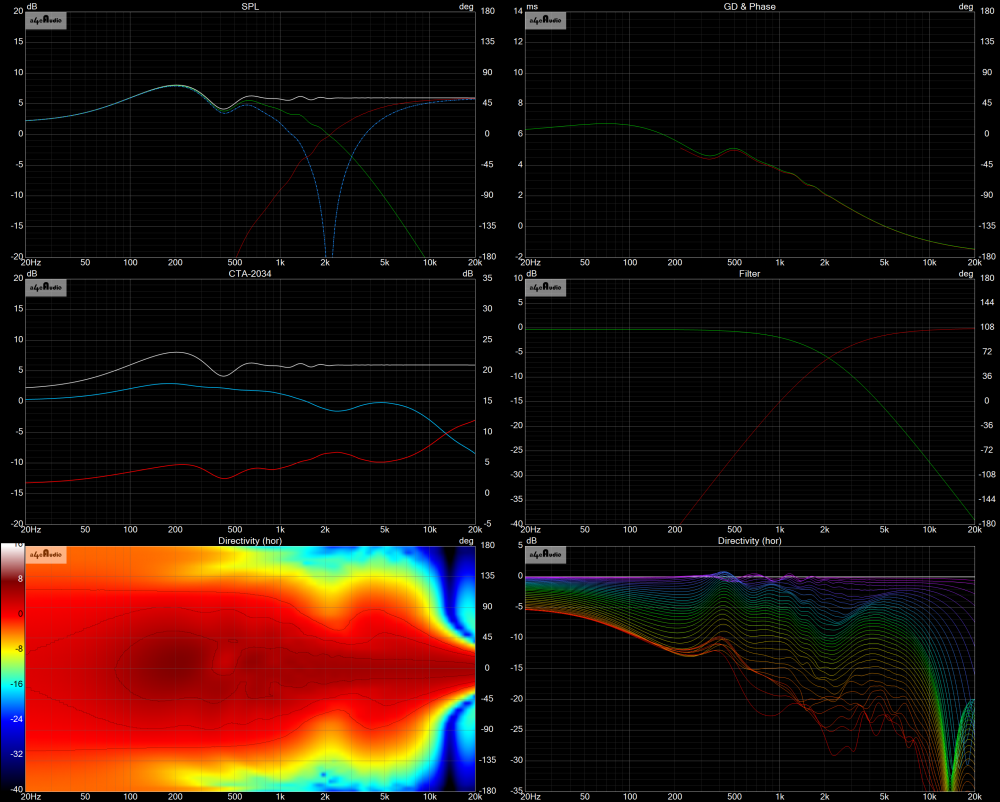
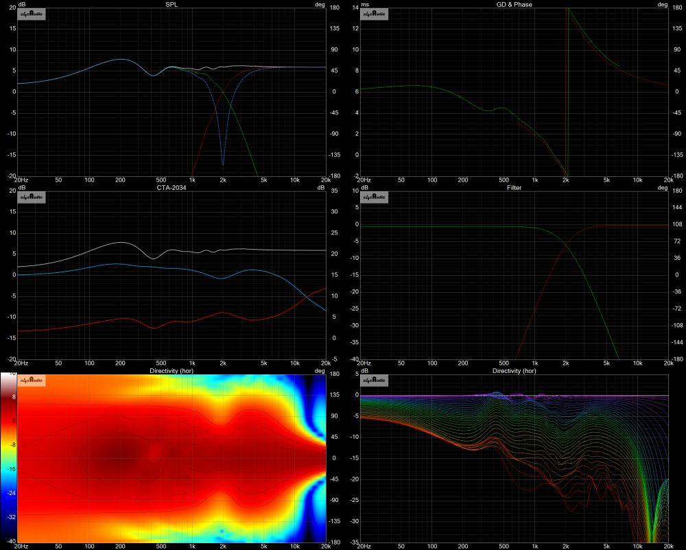
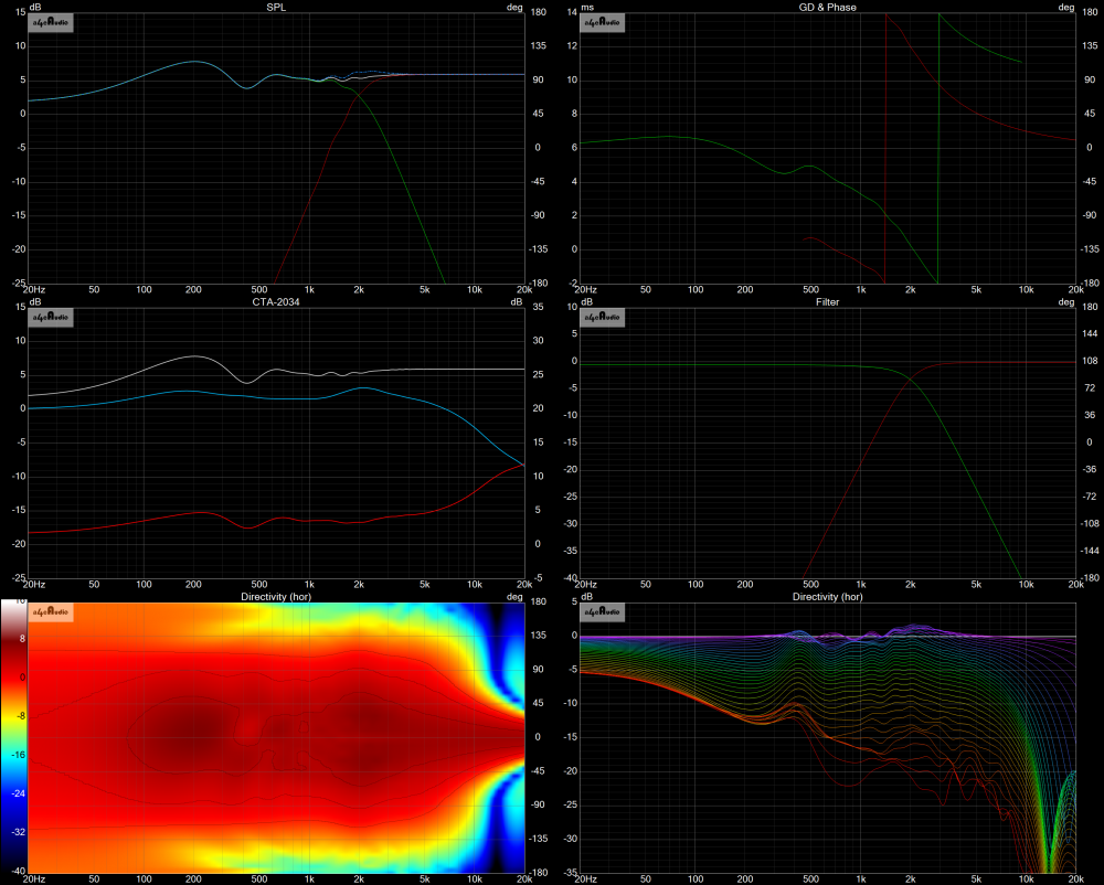
Using a simulated tweeter and woofer with the same Sd as in that link...LR2, LR4 and BW3...(1) Power Response is the blue line in the Left-Middle panes and look just like his. (2) Polar map (lower left) and normalized Line Chart (lower right) show the extra energy he heard above (and below) the crossover point. (3) Deep reverse nulls...except the BW3 case where you can hardly see a difference.
LR2 at 2kHz
LR4 at 2kHz
BW3 at 2kHz
Off-axis "bloom" on 4th LR is a known thing - and is why on-axis dips should be left in place when using that topology.
I generally target 2nd LR or BW3 depending on drivers I am using.
It really is a balancing act. Starting out with good drivers increases options. I have learned much this past year, since using VCad. I have much more to learn. I think it makes sense for me to try 2nd ord. slopes first and if it stresses the tweeter or does not sufficiently reduce woofer breakups, then I need to go higher order. I seem to prefer the sound of crossovers with good phase tracking. I don't pursue the deepest null, but a symmetrical null. I don't have much to share about 3rd ord. except when I tried it months ago it had a pretty high component count and did not control woofer ringing sufficiently. The target slopes are very helpful to me. I then deviate from them slightly to improve phase tracking in the XO region and power response secondarily. I do not understand how increasing driver separation can improve power response, or anything for that matter. So I think I will continue to keep them tight, less than 3/4 wavelength, Until I understand it better. Also please correct me if I am wrong but it seems to me that an easy way to determine the direction of main lobe vertical tilt is to see if the reverse null deepens when you move the mic. up or down.
Kimmo, author of VCAD, posted a "proof of concept" with examples on the long, 100+ page DIYaudio VituixCAD thread. I'll see if I can find it and will post a link. Regarding the main vertical lobe tilt, another way to easily see the tilting direction, either up or down, is by using the "slice of the cow" graph in Vcad. Just open the cow slicer, set the frequency to the xover point, invert the phase of one driver, then watch the lobe shift up or down.
Cow slicer. I get it. I like it.
Nothing is as simple as it first appears.
Found the "Proof of Concept" posts by Kimmosto. They were on the long Diyaudio.com ---> Software --- VituixCAD thread, beginning on page 139 and ending on page 140; thread posts 2770 to 2781. Proof of concept (POC) post #1 is post 2777, POC post #2 is post 2780, and POC post #3 is post 2781. These POC posts were part of a question and answer session between Kimmosto and @DaveFred with respect to how driver spacing distances affect directivity and power response. Try this link:
https://www.diyaudio.com/community/threads/vituixcad.307910/page-140